background image

Electro-Voice

®


 EVID 12.1P User Manual

6

Mounting through a suspended ceiling grid

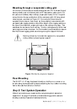
On the rear of the enclosure install and tighten two 3/8-16-thread forged

steel eyebolts (one is included) with a 3/8" flat washer under each. Cut

two pieces of ordinary drop ceiling L angle (wall track) 23 3/4" long and

screw them to the top and bottom of the enclosure with 3/4"-long sheet

metal screws, as shown in Figure 10. Connect all of the wires and

suspend the enclosure, face down, by the eyebolts in accordance with

accepted safe rigging practice. Adjust the length of the rigging cables so

the tips of the installed L angles just rest on the ceiling cross-tees. This

stabilizes the enclosure from rocking. Trim the ceiling panel to fit the new

opening(s) and drop into place. It is the installer’s responsibility to assure

that the chosen rigging points are strong enough to support the load.

Warning: Never try to install this speaker in a suspended

ceiling without proper rigging support!

Floor Mounting

The EVID™ 12.1P may be placed directly on the floor in a corner or on

its side along a straight wall by simply attaching the four rubber mounting

feet to the side that will sit on the floor.

Step 5: Test System Operation

After all connections are made test the complete system operation.

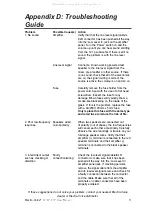
Appendix C on page 10 contains a troubleshooting guide to assist in

locating a variety of speaker related problems.

Figure 10:

 Attach 

L

 Angles to Speaker

L

 angle

Ceiling

tile

Rigging

cables

Acoustic port

Eyebolts

All manuals and user guides at all-guides.com

Summary of Contents for 12" Powered Subwoofer System EVID 12.1P

Page 1: ...Electro Voice EVID 12 1P User Manual EVID 12 1P User Manual All manuals and user guides at all guides com a l l g u i d e s c o m...

Page 2: ...t the Speaker to the Bracket 4 For Corner Mounting 4 For Midwall Mounting 5 Mounting through a Suspended Ceiling Grid 6 Floor Mounting 6 Step 5 Test System Operation 6 Safety Agency Compliance 7 Maint...

Page 3: ...ariety of configurations with the bracket hardware supplied Product Feature Identification The 12 1P subwoofer comes with a dual mode mounting bracket that enables the unit to be easily mounted at eit...

Page 4: ...r Mounting Feet D 2 Speaker Mounting Clips E Eyebolt F Right Angle Power Cord G Owner s Manual H Warranty Card Illustrated in Figure 3 are the major components of the EVIDTM 12 1P subwoofer amplifier...

Page 5: ...ing practices secure one end of a suitable safety line use cable not chain which will rattle to a strong secure point above the speaker a point that can withstand the shock of the falling speaker This...

Page 6: ...cket First remove the two Phillips head screws on the rear of the enclosure Use the supplied eyebolt to mount one mounting clip to the top of the speaker as shown in Figure 8 Check to make sure that t...

Page 7: ...contact with the bracket rungs Slide the enclosure sideways to engage the clip over one bracket rung 1 and while holding it tight against both rungs insert the 3 8 16 thread screw with its clip into t...

Page 8: ...enclosure from rocking Trim the ceiling panel to fit the new opening s and drop into place It is the installer s responsibility to assure that the chosen rigging points are strong enough to support t...

Page 9: ...e of original purchase The Limited Warranty does not apply to burned voice coils or malfunctions such as cone and or coil damage resulting from improperly designed enclosures Electro Voice active elec...

Page 10: ...injury to persons or property or loss of use Some states do not allow the exclusion or limitation of incidental or consequential damages so the above limitation or exclusion may not apply to you Othe...

Page 11: ...best room loading are accomplished with the subwoofer mounted in a corner at a three boundary junction wall wall ceiling or wall wall floor an arrangement also referred to as 1 8 space Mounting at a...

Page 12: ...chemicals as these agents may cause permanent damage to the enclosure After cleaning apply two or more two thin coats of either latex or oil based paint Spraying is recommended but a brush and small...

Page 13: ...fuse with a 4A 250V 20mm x 5mm fuse Only replace this fuse with the same type and rated fuse to reduce the risk of fire 2 Poor low frequency Speakers wired When two speakers are connected out response...

Page 14: ...dBu for Full Output LF Transducer 12 300 mm High Excursion Dual Voice Coil Connectors Line Inputs XLR Balanced Outputs XLR Power Requirement 110 130 VAC 50 60 Hz Enclosure Material MDF Steel Fastener...

Page 15: ...Electro Voice EVID 12 1P User Manual 13 Notes All manuals and user guides at all guides com...

Page 16: ...Department at 800 685 2606 For technical assistance contact Technical Support at 866 78 AUDIO Specifications subject to change without notice All Other International Locations 952 884 4051 Fax 952 736...

Reviews: