indeed set back to factory settings. Do this by re-
entering the calibration procedure. If the 4 mA to 20
mA output signal is at 12 mA (or fairly close) when in
the calibration mode, then you have properly restored
R7 and R8 settings.
D) Continue and complete the calibration procedure for
the process’s fully-closed and fully-open positions.
How to clear-out the existing calibration, and
reprogram the SG1000 (Two methods)
One, 24Vdc power, then press and hold-in the SW2
button while re-applying the +24Vdc power to the SG1000.
Continue to keep the SW2 button pressed-in for a few seconds
until the SG1000 outputs 12 mA, then release the SW2 button.
The old calibration has now been cleared-out, and the SG1000 is
in calibration mode awaiting new calibration.
Or two, while powered, press and hold-in the SW2 button for 5
to 6 seconds to enter calibration mode.
See the “
Calibration Procedure
” section for complete details.
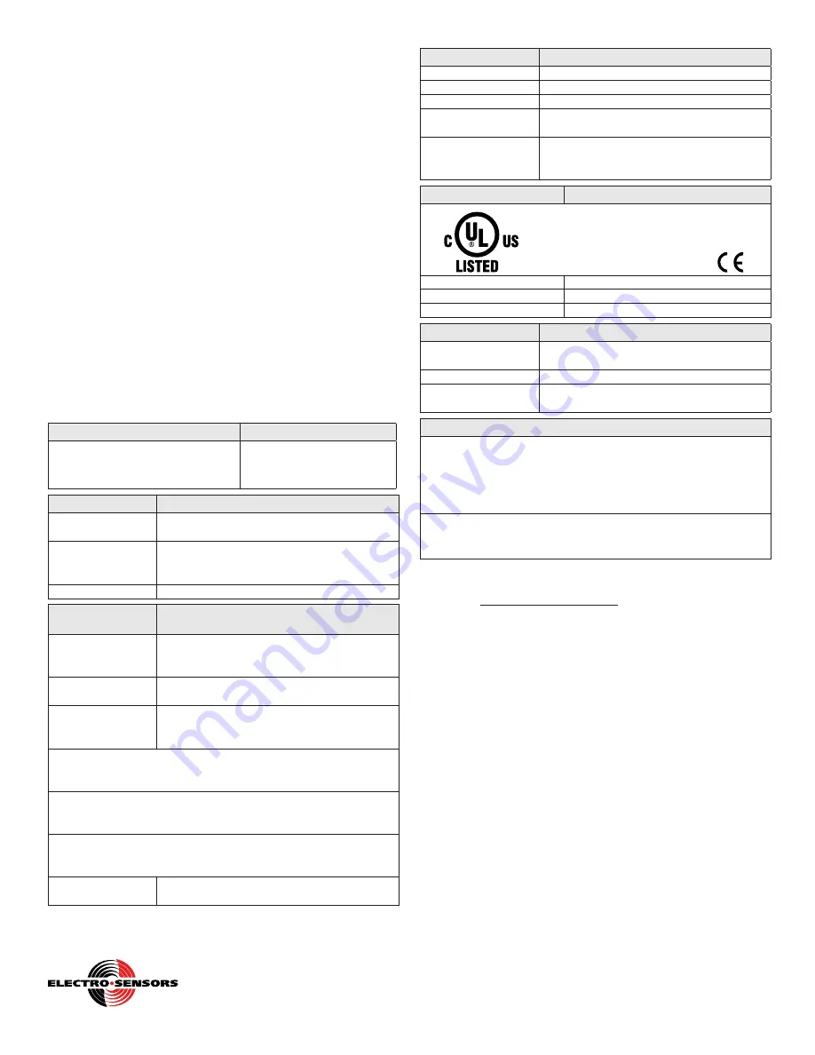
SG1000E General Specifications:
Input Power
Input Current
REQUIRES USER INSTALLED
CLASS 2 ISOLATED
+24 VDC ±10% Power Supply
40mA max (when output
signal is at 20mA)
Input Signal
Parameters
Type
Rotating shaft connected to internal 9 bit, 0 to
511 count, absolute position encoder
Range of Operation
Continuous rotation with no physical end stops.
Calibratible span of 5.6º turn to 130º turn of
output shaft.
Internal Gear Ratio
1:2.75
Analog Output
Signal
Parameters
Type
4-20 mA DC, with programmable end-points:
(4 mA @ user’s fully closed position)
(20 mA @ user’s fully open position)
Accuracy
Resolve to 1 encoder count of calibrated span
position (span from fully closed to fully open).
4-20 mA
Resolution
Varies linearly from best of 0.2% of span,
to worst of 5.0% of span
depending on calibration
0.2% resolution occurs when calibrated at the maximum span of
511 encoder counts, which is a 130º turn of the output shaft. That
is, 1 count out of 511 counts is about 0.002, or 0.2 %
5.0% resolution occurs when calibrated at the minimum span of 21
encoder counts, which is a 5.6º turn of the output shaft. That is, 1
count out of 21 counts is about 0.05, or 5 %
Since the 4-20 mA output has a 16 mA span, a 0.2% resolution
gives an incremental change of 0.032 mA, and a 5.0% resolution
gives an incremental change of 0.800 mA.
Required
impedance
4-20 mA output needs a 250 to 500 Ω load
Mechanical
Parameters
Mounting
End of Shaft, single drilled and tapped hole.
Mounting Threads
3/8-16 UNC x 0.625 in.
Housing Material
Cast Aluminum
Housing Dimensions
Cylindrical, with diameter of 3-11/16”, length
of 7-5/8” (length includes housing & shaft)
Stabilizer Bracket
Mounted semi-rigidly to application’s
framework using two user supplied 5/16”
bolts.
Physical/Enviroment
Parameters
Class I, Groups C, D
Class II, Groups E, F, G
UL File: E249019
Additional Rating
NEMA 4X, Gasket Provided
Temperature Range
-40ºC to +65ºC (-40ºF to +149ºF)
Humidity
0% to 90% non-condensing
Operator Interface
Parameters
One Pushbutton
Enter calibration mode and calibrate for fully
closed/fully open process shaft positions
One Slide Switch
Select calibration direction CW/CCW
Memory
EEPROM retains calibration during power
failure or power shut down
Operation Modes
Normal Operating Mode:
(output signal per process shaft position)
.
- Output: 4 mA to 20 mA signal proportional to process shaft
position, for a properly calibrated SG1000.
- Output: Constant 12 mA for an uncalibrated or miscalibrated
SG1000.
Calibration Mode:
(select calibration direction, calibrate for fully-
closed / fully-open process shaft positions)
.
- Output: Holds at a constant 12 mA in this mode.
Additional Information
To get additional information about the SG1000E, visit our
website at: www.electro-sensors.com
Notice:
Copyright © 2016 Electro-Sensors, Inc. All rights reserved. No part
of this document can be duplicated or distributed without the express
written permission of Electro-Sensors, Inc.
While the information in this manual has been carefully reviewed for
accuracy, Electro-Sensors, Inc. assumes no liability for any errors or
omissions in the information. Electro-Sensors, Inc. reserves the right
to make changes without further notice to any part of this manual or
product described in this manual.
4-4
Free Catalog and Application Assistance
1.800.328.6170
Website: www.electro-sensors.com
990-002440 Revision D


