01/10/2008 2
HI321
MECHANICAL INSTALLATION
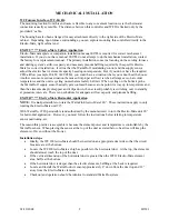
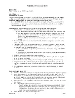
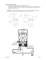
WF Furnace Interface, WF-LGR4
The mounting location from this enclosure is flexible to any convenient location were the thermostat
connection is easily accessible. The distance between this controller and WF II is limited only by the
provided 4’ cable.
The housing has also been arranged for easy attachment directly to the right side of the Electro-Mate
cabinet. Depending upon furnace surroundings, you can explore mounting this controller directly to the
Electro-Mate, right cabinet end.
EM-WU***** Electro-Mate Upflow Application
Electro-Mate
nameplate or companion installation manual EI703 is required for correct mechanical
installation. If you do not have manual #EI703 do not attempt to do the mechanical installation, contact
the factory for a replacement manual. The primary installation concerns focusing on the existing furnace
and ducting system’s airflow capacity and necessary plenum baffling required by the specific Electro-
Mate for correct installation. It is true that the WarmFlo II modulating control and the supply sensor
adjust the electric heat or element capacity based upon temperature. But if you do not have the required
CFM airflow (example 20 kW, 1400 CFM), you could have a situation where you cannot heat the house.
Another even more serious situation (because of improper airflow) is when all stages are on at colder
temperatures and the unit is cycling on mechanical safety hi-limit. When cycling on the hi-limit probe,
the WarmFlo II supply sensor basically gets confused because at one point it is way up in temperature and
then the elements simply disappear and it dips down, the net result probably is switching over to standby
at premature intervals. There is no substitute for adequate airflow capacity and plenum baffling.
EM-WD***** Electro-Mate Horizontal Application
NOTE:
It is
not
permissible to rotate the WarmFlo Electro-Mate 180°. These instructions apply to only
rotating the Electro-Mate unit 90°.
With WarmFlo, IT IS permissible (and authorized by the manufacturer) to turn the Electro-Mate unit 90°
for horizontal application. However, you must follow the instructions below relating to temperature
sensor positioning, etc.
The reason this practice is acceptable is because the element power and temperature is controllable by the
WarmFlo sensor. When placing the sensor at the top of the duct as stated below, heat rise will keep the
elements off even without the blower.
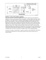
Installation steps
•
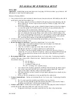
Ideally, the WF II Electro-Mate should be inserted on an appropriate duct side so that the circuit
breakers are at the bottom.
•
Locate the WF II Electro-Mate as high as possible in the horizontal duct. At the top, the elements
should almost touch the top of the duct.
•
If the vertical dimension of the horizontal duct is greater than the WF II Electro-Mate element
area, baffle at the bottom.
•
If the horizontal duct is deeper than the electric elements, baffling at the back is required.
•
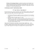
Locate and install the WarmFlo duct sensor approximately 4” down from the duct top and 12”
away from the Electro-Mate elements.
•
Checkout and operation should be identical to standard WarmFlo system.
Summary of Contents for WARMFLO II
Page 28: ......


