12/20/2017
3
EI505
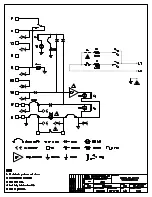
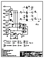
Heater Turn-On Action - The external application of 24 volts AC between "W1" and "C"
pulls K2 relay which acts as a switch for the top 4.6KW element (E1). The red LED next to the
"W1" terminal illuminates. A signal is also diode coupled to K1 and yellow LED illuminates. K1
provides an electrical path between "R" and "G" to operate the air handler blower relay.
With external 24 volt AC between "X" and/or "W2", the same basic action follows switching on
elements E2 and E3. However, these two stages or elements contain an electronic delay of
approximately 10 seconds before K2 and/or K3 pull in. The LED opposite the appropriate terminal
indicates the control system has the appropriate element switch relay closed.
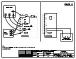
First Level Hi-Limit - The upper off-set hi-limit is connected to the two tab terminals shown on
diagram ES5Ø1 bottom left. If this limit opens due to low airflow, the top PC board red LED is
illuminated and K2, K3, and K4 relays open disconnecting all element power. This is an automatic
reset hi-limit which means it will again close (top LED off) re-establishing the element power. If this
is a cycling function, damage will result to the element relay contacts and/or elements themselves.
Second Level Hi-Limit - The hi-limits in the current carrying leg (between fuse and element) is a
dual function device. The automatic reset internal limit is set 50 below the fuse link internal
function. In other words, if the automatic reset contacts weld, the one time (permanent open circuit)
fuse link will prevent element overheating.
AUX 10 Pin Connector - For special OEM applications and for other plug-in optional devices, the
10 pin connector is represented by the various numbered terminals on the schematic diagram.
19.2KW Model - This is an added element to the 15KW shown. The fourth element has its
own relay tied directly across E3 element power. Whenever K4 switches on the E3 element, the
E4 follows immediately. The 30 amp fuse is changed to a 50 amp fuse.

