background image

14 


REMOVAL AND REFITTING OF THE GLASS 

CANOPY  


WARNING:

 Components within the appliance may have 

sharp edges.  When attempting to remove or refit the 
glass, gloves should be worn to avoid scratches and 

cuts.   


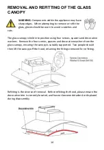
The glass canopy is held into position using four screws, spacers and decorative 

washers.  Remove the four screws, spacers and decorative washers from the 
glass canopy, ensuring the canopy is suitably supported.  Two people should 
then lift the canopy off the hood, retaining the fittings removed for re fitting.  


Refitting is the reverse of removal.  Before refitting the hood, please ensure the 

decorative trim is correctly located, and has not become detached or displaced 
during disassembly.  


Summary of Contents for eiQCURV60BLTOUCH

Page 1: ...ainless Steel eiQCURV60SCTOUCH eiQCURV90SCTOUCH Black eiQCURV60BLTOUCH eiQCURV90BLTOUCH Please read this manual before using or installing the cooker hood and keep it safe for future reference Visit o...

Page 2: ...DIAGRAM 6 OPTIONS FOR VENTILLATION 7 INSTALLATION 8 OPERATION 11 REPLACING THE BULB 12 INSTALLING THE CARBON FILTER OPTIONAL 13 REMOVAL AND REFITTING OF THE GLASS CANOPY 14 CLEANING AND MAINTENANCE 1...

Page 3: ...ttended as it can be a serious fire hazard If the supply cord is damaged it must be replaced by the manufacturer its service agent or a similarly qualified person in order to avoid a hazard The socket...

Page 4: ...ave to be fulfilled The minimum distance between the supporting surface for the cooking vessels on the hob and the lowest part of the hood must be at least 65 cm When the cooker hood is used in conjun...

Page 5: ...5 PARTS DESCRIPTION ILLUSTRATION QTY Cooker Hood 1 Chimney Sections 2 Chimney bracket 2 Hood Installation Plate 1 Screw ST5 50 7 Wall plug 7 Screw ST4 2 9 5 6 Exhaust adaptor 1...

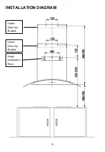
Page 6: ...6 INSTALLATION DIAGRAM Upper Chimney Bracket Lower Chimney Bracket Hood Installation Plate...

Page 7: ...to connect your hood to pre existing 120mm diameter ducting If this is the chosen installation method consideration to the route of the vent pipe should be made prior to installation Please note the...

Page 8: ...ation plates are horizontal to prevent grease from accumulating within the hood Ensure the power has been turned off at the mains before starting installation Connection to the mains supply must be in...

Page 9: ...nd the Upper chimney bracket to the wall in the correct position ensuring the plates are level 4 The 2 air flaps should now be installed on the top of the unit as access is easier before the unit is w...

Page 10: ...ews supplied 7 Hang the hood on the Installation plate and secure to the wall using two screws ST5 50 through the lower chimney bracket into the wall plugs previously inserted 8 If the hood it to be v...

Page 11: ...r indicator will flash To turn the hood off immediately during this time press the power button again INCREASE SPEED BUTTON Press to increase the fan speed The current fan speed is displayed on the pa...

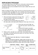
Page 12: ...val and refitting of the glass canopy section 2 Locate the top of the light fitting and squeeze the spring clips while pushing the fitting out of the base of the hood 3 Follow the wire from the light...

Page 13: ...he filter clockwise onto the motor housing TO REMOVE Rotate the filter anti clockwise until it is unscrewed Warning The carbon filter cannot be washed or recycled It should be replaced after approxima...

Page 14: ...sing four screws spacers and decorative washers Remove the four screws spacers and decorative washers from the glass canopy ensuring the canopy is suitably supported Two people should then lift the ca...

Page 15: ...st be kept away from the motor control switch and all electrical components GREASE FILTERS It is recommended that the grease filter is cleaned every two to three months by carrying out the following i...

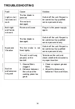
Page 16: ...damaged Switch off the unit Repair to be carried out by qualified service personnel only The fan motor is not fixed tightly Switch off the unit Repair to be carried out by qualified service personnel...

Page 17: ...after cooking MANUFACTURER SUPPORT www electriQ co uk Unit J6 Lowfields Business Park Lowfields Way Elland West Yorkshire HX5 9DA Telephone 0330 390 3061 Office Hours 9 00am to 5 00pm Monday to Frida...

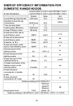
Page 18: ...air pressure at best efficiency point PBEP 142 Pa Maximum air flow Qmax 423 6 m3 h Measured electric power input at best efficiency point WBEP 87 4 W Nominal power of the lighting system WL 1 5W x 2 W...

Reviews: