


akse srl
Via Aldo Moro, 39 42124 Reggio Emilia Italy
Tel. +39 0522 924 244 Fax +39 0522 924 245 [email protected] www.akse.it
P.I. 01544980350 R.E.A. 194296 Cap. Soc. Euro 85.800,00 i.v.
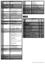
DIGITAL INPUTS
Power supply voltage
(external)
from 10 to 30
Vdc
Current absorbed :
from 2 to 10mA
Max. counting frequency:
10 or 100Hz
Note: for the gas counter, a galvanic insulated
divider following ATEX normative, is needed.
Digital optically insulated outputs,
transistor based, (NPN) following
standard
DIN 43864.
Max voltage applicable
27 Vdc
Max commutable current:
27mA
C
10
1
11
2
12
AUX
IN/OUT
!
Common
12
11
10
DO2
DO1
DI (+)
20
19
DI (-)
+
19
-
20
AUX
IN/OUT
!
INPUT OUTPUT CONNECTIONS
(ONLY FOR VERSION PFA7471-12)
SHUNT CONNECTED BEFORE
SHUNT CONNECTED AFTER
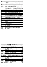
The instrument is equipped with a separate power supply. The power supply terminals
are number as 17 e 18. The max cross-section of the wires is of 2,5 mm
2
if fl exible and 4
mm
2
if rigid.
POWER SUPPLY AND SERIAL LINE CONNECTION
Voltage connection
- Use cables with max cross-section of 2,5 mm
2
if fl exible 4 mm
2
if rigid and connect them to the terminals marked voltage input on the instrument according to the
applicable diagrams that follow.
Connessioni amperometriche
Use SHUNT with a suitable primary range and a 60 o 100 mV secondary. Connect the SHUNT to terminals signed with I1 (S1 e S2) (current input) as in the diagram.
VOLTAGE AND CURRENT CONNECTION
S1 S2 S1 S2 S1 S2 A B
T
10 11 12
17
18
19
20
U1 U2 U3
N
I1
I2
I3
RS-485
AUX
AUX
VOLTAGE INPUT POWER
L
N
FUSE
(50mA T)
230 ÷ 240 V ±10%
Serial RS485 port
A B
T
+
-
3 4 5 6 A B
T
10 11 12
17
18
19
20
+
14
15
-
RS-485
AUX
AUX
VOLTAGE INPUT POWER
CURRENT INPUT
+
-
SHUNT
+
-
3 4 5 6 A B
T
10 11 12
17
18
19
20
+
14
15
-
RS-485
AUX
AUX
VOLTAGE INPUT POWER
CURRENT INPUT
+
-
SHUNT
INPUT AND OUTPUT CONNECTION EXAMPLES
S1 S2 S1 S2 S1 S2 A B
T
10 11 12
17
18
19
20
U1 U2 U3
N
I1
I2
I3
RS-485
AUX
AUX
VOLTAGE INPUT POWER
NO
C
NC
NO
C
NC
Max
27 Vdc
27 mA
(-)
(+)
230 Vac
FROM:
- TRANSDUCER WITH CONTACT CLEAN
- GME
- STATE ON-OFF
- STATE ALARMS
R
e
l
a
y
R
e
l
a
y
Power
Supply
S1 S2 S1 S2 S1 S2 A B
T
10 11 12
17
18
19
20
U1 U2 U3
N
I1
I2
I3
RS-485
AUX
AUX
VOLTAGE INPUT POWER
Es.
Input M8 Supervisor
1 2 C
C
3 4
(-)
(+)
(-) (+) (+)
Es. PLC
Out PLC
Comune
Subject to modifi cation without notice.
Edition 06-10-2010
Made
in
Italy
Pensato, progettato e prodotto in Italia
Engineered and manufactured in Italy


