background image


27 


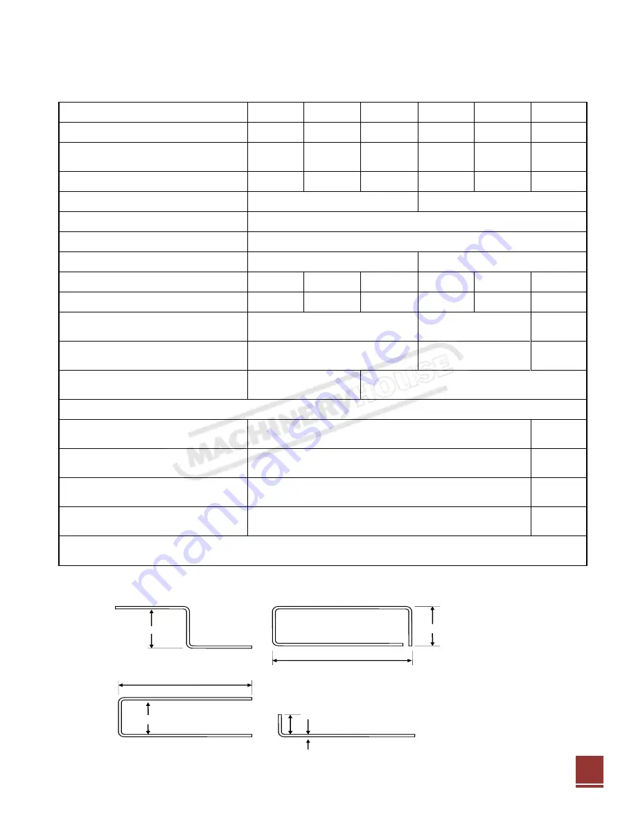
SPECIFICATION SHEET


Model 

EB0625 

EB1000 

EB1250 

EB2000 

EB2500 

EB3200 

Weight of Machine 

Kg 

72 

110 

150 

270 

315 

380 

Nominal Capacity 

(length 

x thickness)


mm 

0625 

x1.6 

1000 x 

1.6 

1250 x 

1.6 

2000 x 

1.6 

2500 x 

1.6 

3200 x 

1.2 

Clamping Force 

Tons 

4.5 

12 

10 

Electricity Supply 


1 phase, 220/240vac, 10A 

1 phase, 220/240vac, 16A 

Duty Cycle  

30 

Protection 

°C 

Thermal cut-out 70°/80°C 

Foot Switch 


No 

Standard 

Bending-edge Length 

mm 

670 

1050 

1300 

2090 

2590 

3290 

Distance between Lifters 

mm 

630 

1010 

1260 

2028 

2528 

3228 

U-Channel bends,


minimum spacing


mm 

16*** 

19*** 

45*** 

Closed channel,


minimum 

internal


mm 

99 x 27*** 

114 x 22*** 

114 x 

45*** 

Z-reverse bends,


minimum 

spacing


mm 

35** / 16* 

36** / 18* 

Thickness Capacities, full length


(material thickness can increase depending on the length of bend)


    …Mild steel 

mm 

1.6** / 1.2* 

1.2** / 
1.0* 

    …Aluminium (medium-
hard) 

mm 

1.6** / 1.2* 

1.2** / 
1.0* 

    …Copper, Zinc, Brass 
(medium-hard) 

mm 

1.6** / 1.2* 

1.2** / 
1.0* 

    …Stainless steel 

mm 

1.0** / 0.9* 

0.9** / 
0.8* 

*** with standard full length clamp bar            **with bending beam extension bar        *extension bar 

removed 


Bending dimensions. 


Refer to Chart


19mm 
(min) 

19mm (min) 

- 98mm (min) Standard Clampbar 
- 49mm (min) Narrow Clampbar 

19mm (min) 

Unlimited 

27

Instruction Manual for EB2500 (S5321)

24/8/2012

Summary of Contents for EB0625

Page 1: ...EB2500 Magnetic Panbrake 240V 2500 x 1 6mm INSTRUCTION MANUAL S5321 1 Instruction Manual for EB2500 S5321 24 8 2012 ...

Page 2: ... to check using the machine 19 Maintenance 20 Adjusters 20 Hinge lubrication 20 Working surfaces 20 Trouble shooting 20 Full clamping not operating 21 Clamp bar not being released 21 Problems with the bending of heavy gauge sheet metal 22 EB 625 and EB1000 panel 23 EB 2000 EB3200 Wire panel 24 EB 0625 EB1250 Circuit diagram 25 EB 2000 EB2500 and EB3200 circuit diagram 26 Specification sheet 27 Dim...

Page 3: ... can be folded on the EB3200 across the full length of the machine The EB625 EB1000 EB1250 EB2000 and EB2500 machines fold material of up 1 6mm thickness These multi purpose machines bend sheet metal of lengths 625mm 1000mm 1250mm 2000mm 2500mm and 3200mm respectively The ELECTRABRAKE magnetic clamping system replaces the bulky clamping structure used in conventional folding machines The small com...

Page 4: ...4 4 Instruction Manual for EB2500 S5321 24 8 2012 ...

Page 5: ...5 5 Instruction Manual for EB2500 S5321 24 8 2012 ...

Page 6: ...6 6 Instruction Manual for EB2500 S5321 24 8 2012 ...

Page 7: ... OR 1 828 METRES to an Electramagnetic machine or anything that has an electrical field 1 Strong electromagnetic fields can cause electromagnetic interference 2 EMI can stop the pacemaker from sensing your heart s rhythm PACEMAKER PROTECTION 7 Instruction Manual for EB2500 S5321 24 8 2012 ...

Page 8: ...tand 8 Remove the rear access cover to gain access to the electrical unit By removing the four pan head screws Connect the adjoining matching plug leads from the magnetic coil and PC board Refit the rear access cover 9 On the EB625 the tray is in two halves First join the two halves of the tray using the two M6 pan head screws and nuts Now using two M8 x 12 cap head screws attach the tray to the b...

Page 9: ...the magnet body 9 Use three M8 x 12 cap head screws to attach the tray to the back of the magnet body between the two back stop bars Place the rubber mat in the tray 10 Open the bending beam to gain access to the back of the bending beam so that you can attach the handle 11 Use two M8 x 20 cap head screws per handle to attach the handles to the bending beam 12 The handle with the angle scale is at...

Page 10: ... attach the four backstop bars to the back of the magnet body 11 Use one M8 x 20 cap head screw with lock nut per lifter handle to attach lifter handles to the back of the shaft located at the outside of the columns 12 Open the bending beam to gain access to the back of the bending beam so that you can attach the handles 13 Use two M8 x 20 cap head screws per handle to attach the handles to the be...

Page 11: ...To achieve and perfect bend set a fractionally larger gap than the depth of the sheet metal between the edge of the clamp bar and the face of the bending beam Place sheet metal under clamp bar the backstop can be used if needed Lift handles or push down the clamp bar onto the sheet metal The machine will not turn ON until the clamp bar is within 5mm above the surface bed due to the interlock The i...

Page 12: ...ng a long surface to use as a reference The extension pies from the bending beam could be used Use a strip of sheet metal of the same thickness as the work piece if a backstop is required under the clamp bar HOW TO FOLD A LIP Folding the lip will depend on the sheet metal thickness and the length and width Lightweight sheet metal up to 0 8mm 1 Carry out instruction for standard bending and continu...

Page 13: ...at the clamp bar does not overlap the machines front pole A ii Ensure that the rolling pipe is resting on the front pole of the machine B It must not sit on the aluminium surface of the machine iii The clamp bar provides a magnetic pathway for the rolling bar Folding round a pipe 2 Wrap the sheet metal around the rolling bar as far as possible 13 Instruction Manual for EB2500 S5321 24 8 2012 ...

Page 14: ... the clamp bar with the folded lip end toward you Tilt clamp bar and line up bend marked 2 Bend to 90 degrees as shown in drawing below Turn sheet metal over and continue with steps marked 3 4 and 5 bent to 90 degrees Roll the remaining piece around a 25 mm diameter round bar see How to make a rolled edge See drawing below for completed job 200 8 45 95 117 190 335 Bend 2 Bend 4 90 Bend 3 90 Bend 1...

Page 15: ...ger lengths use several clamp pieces to fit the required length Clamp pieces can be plugged together for repeat bending when making a single unit A slotted clamp bar must be used for boxes or trays with shallow sides Refer to HOW TO MAKE TRAYS LIPPED BOXES 1 Use the set of standard short clamp bars to make rectangular lipped boxes i e 98mm 2 Choose the short clamp bar with at least a lip width sho...

Page 16: ...sheet metal as shown on drawing 3 For folds on side panels as per drawing use the narrow flange of the end piece of the clamp bar 4 Join the box FLANGED BOXES WITH PLAIN CORNERS To make plain cornered boxes the length and width should not exceed the clamp bar width of 98mm Outside flanges are also used when making top hat sections 1 Mark up sheet metal as per drawing below 2 Use the full length cl...

Page 17: ... 2 Form all tab folds to 90deg marked A at the one end of the full length clamp bar by inserting the tab under the clamp bar 3 Use the same end of the clamp bar and fold B to 45deg by inserting the side of the box instead of the bottom of the box under the clamp bar 4 Form the flange fold C to 90deg at the other end of the clamp bar 5 Complete folds B to 90deg By using suitable short clamp bars 6 ...

Page 18: ...s Specification sheet indicate shortest and longest tray sizes that can be accommodated by the slotted clamp bar To fold shallow tray 1 First fold two opposite sides and the corner tabs by using the slotted clamp bar ignore the slots they will have no effect on the finished folds 2 Select two slots to fold the remaining two sides Line up the left side of the tray with the left slot and check if th...

Page 19: ...ck the gap between the working surface of the bending beam and the edge of the clamp bar Set the gap at 1mm on each side by using the clamp bar adjusters A feeler gauge or scrap piece of metal can be used The gap must be the same along the edge of the clamp bar Variations can be within 0 2mm The gap must not exceed 1 2mm and be less than 0 8mm Should the adjustors not be the same at each end they ...

Page 20: ...re both set so that the single pop mark is uppermost Adjuster set to 1mm HINGE LUBRICATION Grease all hinges once per month Hinge WORKING SURFACES Bare working surface may become rusty or tarnished Recondition by filling off and clean up surfaces with emery paper Use an anti rust spray TROUBLE SHOOTING Prior to ordering a replacement electrical unit from the manufacturer please check the following...

Page 21: ...am is lifted this rotates the brass section which in turn depresses the micro switch You should be able to hear the micro switch click on and off Failing this adjust the clutching force This can be done by ensuring that the two M8 cap head screws at either end of the actuator shaft are secured This adjustment should ensure that the actuator rotates and clutches however if you are still unable to h...

Page 22: ...ips are being bent over the full length of the machine please note that the machine is not equipped to do this Should the work piece not be level i e have a welded seam or a joint it may not be possible to bend the work piece Ensure that all spaces under the clamp bar are filled with flat pieces of scrap metal 22 Instruction Manual for EB2500 S5321 24 8 2012 ...

Page 23: ...23 EB0625 AND EB1000 PANEL 23 Instruction Manual for EB2500 S5321 24 8 2012 ...

Page 24: ...24 EB 2000 TO 3200 WIRE PANEL 24 Instruction Manual for EB2500 S5321 24 8 2012 ...

Page 25: ...25 EB 0625 1250 CIRCUIT 25 Instruction Manual for EB2500 S5321 24 8 2012 ...

Page 26: ...26 EB 2000 EB3200 CIRCUIT DIAGRAM 26 Instruction Manual for EB2500 S5321 24 8 2012 ...

Page 27: ...1260 2028 2528 3228 U Channel bends minimum spacing mm 16 19 45 Closed channel minimum internal mm 99 x 27 114 x 22 114 x 45 Z reverse bends minimum spacing mm 35 16 36 18 Thickness Capacities full length material thickness can increase depending on the length of bend Mild steel mm 1 6 1 2 1 2 1 0 Aluminium medium hard mm 1 6 1 2 1 2 1 0 Copper Zinc Brass medium hard mm 1 6 1 2 1 2 1 0 Stainless s...

Page 28: ...28 DIMENSIONAL SPECIFICATIONS EB625 DIMENSIONAL SPECIFICATIONS EB1000 28 Instruction Manual for EB2500 S5321 24 8 2012 ...

Page 29: ...29 DIMENSIONAL SPECIFICATIONS EB1250 29 Instruction Manual for EB2500 S5321 24 8 2012 ...

Page 30: ...30 DIMENSIONAL SPECIFICATIONS EB2000 DIMENSIONAL SPECIFICATIONS EB2500 30 Instruction Manual for EB2500 S5321 24 8 2012 ...

Page 31: ...31 DIMENSIONAL SPECIFICATIONS EB3200 31 Instruction Manual for EB2500 S5321 24 8 2012 ...

Page 32: ...tall operate maintain or service your ELECTRABRAKE machine that you strictly adhere to each of the following Always wear gloves A sharp edge on a machine or work peace can hurt and or cut your hands Ensure gloves are worn at all times as the magnet body will become hot and can cause minor burns Ensure that your machine is adheres to the assembly instructions Be sure to wear safety boots You can ca...

Page 33: ...he ground wire from a three prong power cord or any other ground wires from the machine Do not perform any alterations to any machine switches components or features Before repairing the machine replace any damaged pinched or frayed wires Make sure all electrical connections within the unit are correctly and securely connected Moisture Protection Ordinary This Product is not suitable for out door ...

Page 34: ...36 FRAME ASSEMBLY AND PARTS LIST EB2000 EB2500 EB3200 34 Instruction Manual for EB2500 S5321 24 8 2012 ...

Page 35: ...37 35 Instruction Manual for EB2500 S5321 24 8 2012 ...

Page 36: ... ELECTRICAL UNIT 1 EB 012 STOP COLLAR 1 EB 110 D FUSE 3 VARIANT 10A WA 1 EB 089 CLAMP BAR 625 ASSY 1 EB 020 CLAMP BARS SHORT SET 1 ELEC476 CRIMP TERMINAL PINS 29 2 EB 111 BACK STICKER FOR ELECTRABRAKE 1 EB 110 FRONT STICKER FOR ELECTRABRAKE 1 EB 112 LEFT STICKER FOR ELECTRABRAKE 1 EB 113 RIGHT STICKER FOR ELECTRABRAKE 1 ELEC474 SOCKET HOUSING 3 PIN 29 1 FW M10 EG M10X1 2 FLAT WASHER GAL 4 FW M6 EG...

Page 37: ...B 019 CLAMP BAR 600 LONG 1 EB 020 CLAMP BARS SHORT SET 1 EB ELEC 1000 PCB 1000 ELECTRICAL UNIT WI 1 ELEC474 SOCKET HOUSING 3 PIN 29 1 ELEC476 CRIMP TERMINAL PINS 29 2 FW M8 EG M8X1 2 FLAT WASHER GAL 3 P O WAS 8MM 8MM PUSH ON FIX WASHER 1 EB 1000 CRATE 1170X270X270 WOODEN CRATE 1 EB 110 FRONT STICKER FOR ELECTRABRAKE 1 EB 111 BACK STICKER FOR ELECTRABRAKE 1 EB 112 LEFT STICKER FOR ELECTRABRAKE 1 EB...

Page 38: ... FRONT STICKER FOR ELECTRABRAKE 1 EB 111 START LABEL 1 EB 111 BACK STICKER FOR ELECTRABRAKE 1 EB 112 LEFT STICKER FOR ELECTRABRAKE 1 EB 113 RIGHT STICKER FOR ELECTRABRAKE 1 EB 225 RULER EB1250 ALUMINIUM RULER 1 EB 019 CLAMP BAR 600 LONG 1 EB 020 CLAMP BARS SHORT SET 1 EB ELEC 1250 PCB 1250 ELECTRICAL UNIT WI 1 EB HAR 1250 S 1250 HARNESS SHORT 1 EB HARNESS 1250 1250 ELECTRICAL HARNESS 1 ELEC474 SOC...

Page 39: ...D 1 EB 110 FRONT STICKER FOR ELECTRABRAKE 1 EB 110 B FUSE 3 VARIANT 20A WA 1 EB 111 START LABEL 2 EB 111 BACK STICKER FOR ELECTRABRAKE 1 EB 112 LEFT STICKER FOR ELECTRABRAKE 1 EB 113 RIGHT STICKER FOR ELECTRABRAKE 1 EB 079 CLAMP BAR FULL LENGTH 1 EB 019 CLAMP BAR 600 LONG 1 EB 083 FOOT SWITCH ASSY 1 EB 020 CLAMP BARS SHORT SET 1 EB 021 CLAMP BAR 1160 1 EB ELEC 2 0 PCB 2MT ELECTRICAL UNIT 1 EB HAR ...

Page 40: ...LECTRABRAKE 1 EB 110 B FUSE 3 VARIANT 20A WA 1 EB 111 START LABEL 2 EB 111 BACK STICKER FOR ELECTRABRAKE 1 EB 112 LEFT STICKER FOR ELECTRABRAKE 1 EB 113 RIGHT STICKER FOR ELECTRABRAKE 1 EB 225 RULER EB1250 ALUMINIUM RULER 1 EB 018 CLAMP BAR FULL LENGTH 1 EB 019 CLAMP BAR 600 LONG 1 EB 020 CLAMP BAR SHORT SET 1 EB 021 CLAMP BAR 1160 1 EB 083 FOOT SWITCH ASSY 1 EB ELEC 2 5 PCB 2 5MT ELECTRICAL UNIT ...

Page 41: ...KER FOR ELECTRABRAKE 1 EB 110 B FUSE 3 VARIANT 20A WA 1 EB 111 START LABEL 2 EB 111 BACK STICKER FOR ELECTRABRAKE 1 EB 112 LEFT STICKER FOR ELECTRABRAKE 1 EB 113 RIGHT STICKER FOR ELECTRABRAKE 1 EB 225 RULER EB1250 ALUMINIUM RULER 1 EB 026 CLAMPBAR FULL LENGTH 1 EB 019 CLAMPBAR 600 LONG 1 EB 020 CLAMPBARS SHORT SET 1 EB 021 CLAMPBAR 1160 1 EB 083 FOOT SWITCH ASSY 1 EB 118 SUPPORT LEG ASSEMBLY 2 EB...

Reviews: