background image

MINIguard Conductivity Indicator

Page 15

www.elector-water-treatment.com

EN

3.6 Setting the measuring range

The device offers four selectable measuring ranges 
which define the switching points between the 
green, yellow and red flashing LEDs.

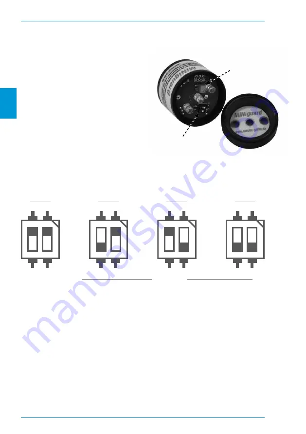
To set the measuring range, open the housing as 
described under 3.3.

There is a dip-switch on the top of the circuit board. 
The respective measuring ranges can be activated 
via the different switch positions.

ATTENTION! There is a trimming potentiometer on 
the printed circuit board. This must not be adjusted 
under any circumstances, as this changes the 
measuring cell factor.

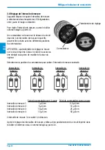
Choose the position of the dip switches to activate the desired measurement range.


Switch-point green to yellow 

Switch-point yellow to red

Range 1: 

1 µS/cm 

2,5 µS/cm

Range 2: 

5 µS/cm 

10 µS/cm

Range 3: 

10 µS/cm 

25 µS/cm

Range 4: 

10 µS/cm 

50 µS/cm

Measuring range 3 is activated when delivered.

After setting the measuring range, make sure that the circuit board is correctly positioned in the 
housing and close it as described under 3.3.

Dip-switch

Trimming potentiometer

1

ON

2

1

ON

2

1

ON

2

1

ON

2

Range 1

Range 2

Range 3

Range 4

Summary of Contents for MINIguard

Page 1: ...e 05 2022 Änderungen vorbehalten Subject to change Sous réserve de modifications Leitfähigkeitsindikator für die Vollentsalzung mit Ionenaustauscherharzen Conductivity indicator for deionization with ion exchange resins Indicateur de conductivité pour la déionisation avec des résines échangeuses d ions ...

Page 2: ...hreibung 2 2 Systemübersicht 2 1 Aufbau des Messgerätes 3 2 2 Installation 4 2 3 Technische Daten 4 3 Anwendungshinweise 3 1 Verwendung 5 3 2 Wartung 5 3 3 Öffnen und Schließen des Messgerätes 6 3 4 Verdrehen der Verschlusskappe 6 3 5 Austausch der Batterie 6 3 6 Einstellen des Messbereiches 7 3 7 Messtoleranzen 8 3 8 Entsorgung 8 ...

Page 3: ...verhütung und für sicherheits und fachgerechtes Arbeiten zu beachten Diese Betriebsanleitung muss ständig am Einsatzort verfügbar sein Die jeweils gültigen nationalen und internationalen Sicherheitsvorschriften sind einzuhalten Jeder Bediener Betreiber ist für die Einhaltung der für ihn geltenden Vorschriften selbst verantwortlich und muss sich selbstständig um die jeweils neusten Vorschriften bem...

Page 4: ...essgerätes 3 4 Überwurfmutter 3 4 Anschlussgewinde flachdichtend Elektronikgehäuse POM mit 1 4 Außengewinde und Edelstahl Leitfähigkeitssensor auf Durchflussmesszelle aufgeschraubt dichtend mit O Ring grüne LED Durchflussmesszelle PVC U oder Edelstahl gelbe LED rote LED Verschlusskappe des Elektronikgehäuses ...

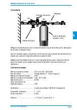
Page 5: ...gerät die Rohrleitung abgesperrt werden kann und dadurch ein Ausbau des Messgerätes für Wartungszwecke jederzeit möglich ist 2 3 Technische Daten Material Durchflusszelle PVC U oder Edelstahl 1 4404 V4A Anschlussgewinde 3 4 Außengewinde 3 4 Überwurfmutter Material Elektronikgehäuse POM Material Leitfähigkeitssensor Edelstahl 1 4571 V4A Material Dichtungen EPDM Schutzklasse Elektronikgehäuse IP56 S...

Page 6: ...st und sich die Leitfähigkeitsmesszelle in Kontakt mit Luft befindet muss die grüne Leuchtdiode blinken Wenn dies nicht der Fall ist besteht zwischen den Messelektroden ein elektrisch leitender Kontakt oder es liegt eine Störung vor 3 2 Wartung MINIguard ist wartungsarm Zur Gewährleistung einer einwandfreien Funktion sollten die Gummidichtungen und die Kunststoffgewinde regelmäßig geprüft werden D...

Page 7: ... Einrasten vernehmen Beachten Sie dass der Kunststoff des Gehäuses durch scharfkantige Gegenstände oder durch zu hohe Krafteinwirkung beschädigt werden kann 3 4 Verdrehen der Verschlusskappe Die Verschlusskappe kann verdreht und die Position der Leuchtdioden an die bauliche Situation angepasst werden ACHTUNG Die Verschlusskappe sollte nicht mehr als 360 gedreht werden Ein Überdrehen kann zu einem ...

Page 8: ...findet sich ein Trimmpotentiometer Dieses darf keinesfalls verstellt werden da hierdurch der Messzellenfaktor verändert wird Wählen Sie die Position der Dipschalter um den gewünschten Messbereich zu aktivieren Umschaltpunkt grün nach gelb Umschaltpunkt gelb nach rot Messbereich 1 1 µS cm 2 5 µS cm Messbereich 2 5 µS cm 10 µS cm Messbereich 3 10 µS cm 25 µS cm Messbereich 4 10 µS cm 50 µS cm Der Me...

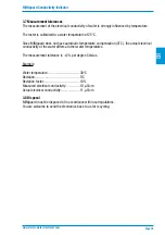
Page 9: ...atische Temperaturkompensation verfügt weicht die tatsächliche elektrische Leitfähigkeit des Wassers bei anderen Wassertemperaturen ab Die Messtoleranz beträgt 2 je Grad Celsius Beispiel Wassertemperatur 30 C Abweichung 5 C Abweichungsfaktor 10 Gemessene elektrische Leitfähigkeit 10 µS cm Tatsächliche elektrische Leitfähigkeit 11 µS cm 3 8 Entsorgung MINIguard muss gemäß der örtlichen Bestimmungen...

Page 10: ...iption 10 2 System Overview 2 1 Construction of the indicator 11 2 2 Installation 12 2 3 Technical specifications 12 3 Application Instructions 3 1 Usage 13 3 2 Maintenance 13 3 3 Opening and closing the device 14 3 4 Twisting the cap 14 3 5 Battery replacement 14 3 6 Setting the measuring range 15 3 7 Measurement tolerances 16 3 8 Disposal 16 ...

Page 11: ...ing instructions the current and locally applicable regulations for accident prevention and for safe and professional work must be observed These operating instructions must always be available at the place of use The applicable national and international safety regulations must be observed Each user is responsible for complying with the regulations that apply to him and must independently strive ...

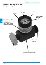
Page 12: ...ew 3 4 union nut 3 4 male thread flat sealing Electronics housing POM with 1 4 male thread and stainless steel conductivity sensor assembled on flow cell sealed with o ring gasket green LED Flow cell PVC U or stainless steel yellow LED red LED Electronics housing cap 2 1 Construction of the indicator ...

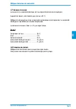
Page 13: ...y remove the device for maintenance purposes 2 3 Technical specifications Material of flow cell PVC U or Stainless steel 1 4404 V4A Connection 3 4 male thread 3 4 union nut Material of electronics housing POM Material of conductivity sensor Stainless steel 1 4571 V4A Material Gaskets EPDM Protection class IP56 Power supply Lithium button cell CR2450 3V replaceable Operating temperature 1 40 C Oper...

Page 14: ... the conductivity cell is in contact with air the green LED should flash If this is not the case there is an electrically conductive contact between the measuring electrodes or there is a fault 3 2 Maintenance MINIguard requires little maintenance To ensure proper functioning the rubber gaskets and the plastic threads should be checked regularly Depending on the intensity of use the electronics ho...

Page 15: ...ess the sealing cap down until you hear it click into place Please note that the plastic of the housing can be damaged by sharp edged objects or by excessive force 3 4 Twisting the cap The sealing cap can be twisted and the position of the light emitting diodes can be adjusted to the structural situation ATTENTION The locking cap should not be rotated more than 360 Over twisting can cut internal w...

Page 16: ... trimming potentiometer on the printed circuit board This must not be adjusted under any circumstances as this changes the measuring cell factor Choose the position of the dip switches to activate the desired measurement range Switch point green to yellow Switch point yellow to red Range 1 1 µS cm 2 5 µS cm Range 2 5 µS cm 10 µS cm Range 3 10 µS cm 25 µS cm Range 4 10 µS cm 50 µS cm Measuring rang...

Page 17: ... not have automatic temperature compensation ATC the actual electrical conductivity of the water differs at other water temperatures The measurement tolerance is 2 per degree Celsius Example Water temperature 30 C Deviation 5 C Deviation factor 10 Measured electrical conductivity 10 µS cm Actual electrical conductivity 11 µS cm 3 8 Disposal MINIguard must be disposed of in accordance with local re...

Page 18: ...ème 2 1 Composition de l appareil de mesure 19 2 2 Installation 20 2 3 Données techniques 20 3 Consignes d utilisation 3 1 Utilisation 21 3 2 Maintenance 21 3 3 Ouverture et fermeture de l appareil de mesure 22 3 4 Rotation du capuchon 22 3 5 Remplacement de la pile 22 3 6 Réglage de l intervalle de mesure 23 3 7 Tolérances de mesure 24 3 8 Élimination des déchets 24 ...

Page 19: ...s en vigueur au niveau local en matière de prévention des accidents de sécurité au travail et de conformité aux règles de l art Ce manuel de l utilisateur doit être disponible en permanence sur le lieu d utilisation Les consignes de sécurité en vigueur au niveau national et international doivent être respectées Chaque utilisateur exploitant est lui même responsable du respect des règles qui lui so...

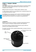
Page 20: ...2 1 Composition de l appareil de mesure Écrou chapeau Raccord fileté à joint plat Boîtier électronique POM avec filetage extérieur et capteur de conductivité en inox vissé sur capteur de débit étanchéité par joint torique LED verte Capteur de débit PVC U ou inox LED jaune LED rouge Capuchon du boîtier électronique ...

Page 21: ...pareil de mesure puisse être coupée et que l appareil puisse ainsi être démonté à tout moment aux fins de maintenance 2 3 Données techniques Matériau du capteur de débit PVC U ou inox 1 4404 V4A Raccords filetés Filetage extérieur Écrou chapeau Matériau du boîtier électronique POM Matériau du capteur de conductivité Inox 1 4571 V4A Matériau des joints EPDM Classe de protection du boîtier électroni...

Page 22: ... conductivité est en contact avec l air la diode lumineuse verte doit clignoter Si ce n est pas le cas un contact électriquement conducteur existe entre les électrodes ou on est en présence d un dysfonctionnement 3 2 Maintenance MINIguard ne nécessite que peu de maintenance Pour garantir un fonctionnement parfait les joints en caoutchouc et les filetages en plastique doivent être vérifiés régulièr...

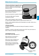
Page 23: ...ur le capuchon jusqu à entendre un clic Attention la matière plastique du boîtier peut être endommagée avec des objets à arêtes vives ou en appuyant trop fort 3 4 Rotation du capuchon Le capuchon peut être tourné et la position des diodes peut être adaptée à la situation de l installation ATTENTION le capuchon ne doit jamais être tourné de plus de 360 Forcer peut sectionner les câbles à l intérieu...

Page 24: ...ui ci ne doit en aucun cas être déréglé sous peine de modifier le facteur du capteur Sélectionnez la position du commutateur pour activer l intervalle de mesure souhaité Point de commutation vert à jaune Point de commutation jaune à rouge Intervalle de mesure 1 1 µS cm 2 5 µS cm Intervalle de mesure 2 5 µS cm 10 µS cm Intervalle de mesure 3 10 µS cm 25 µS cm Intervalle de mesure 4 10 µS cm 50 µS c...

Page 25: ...une compensation automatique de la température la conductivité électrique de l eau diffère avec d autres températures La tolérance de mesure s élève à 2 par degré Celsius Exemple Température de l eau 30 C Écart 5 C Facteur de diversité 10 Conductivité électrique mesurée 10 µS cm Conductivité électrique réelle 11 µS cm 3 8 Élimination des déchets MINIguard doit être éliminé dans le respect des règl...

Page 26: ...MINIguard Indicateur de conductivité Page 25 www elector traitementdeleau fr FR ...

Page 27: ...MINIguard Indicateur de conductivité Page 26 www elector traitementdeleau fr FR ...

Page 28: ...elector GmbH Düsseldorfer Straße 287 42327 Wuppertal Deutschland Telefon 49 0 2058 1790863 Telefax 49 0 2058 1790864 E Mail info elector gmbh de Internet www elector gmbh de ...

Reviews: