background image


3.  GENERAL INSTALLATION INSTRUCTION 


3.1 Mounting instructions  


The  device  should  be  either  installed  horizontally  or  vertically  allowing  enough  space  for  the  pipe 
connections,  wiring  and  maintenance  of  lamps/quartz  sleeve(s).  It  should  be  firmly  secured,  using  the 
fixing kit provided, to a solid wall. 


NOTE: 

When mounting the UV, it is essential to leave a clearance space of at least 1 metre 
from  one  side  of  the  unit  to  allow  access  to  replace  the  lamp(s)  and/or  quartz 
sleeve(s)  when  required.  Both  the  lamps  and  the  quartz  sleeve  can  be  replaced 
from either end of the unit; if installing vertically the 1m clearance space must be 
above or below the unit, if installing horizontally the 1m clearance space must be to 
the left or right of the unit. 


WARNING: 

The device must be installed within a dry, permanent weather-proof area. In any 
case where water or moisture enters the enclosure the warranty will be void.


Caution:  

If the device is unused during the winter months, it  must be drained to prevent frost 
damage. Water must not be allowed to freeze inside the unit as this will cause severe 
damage. 


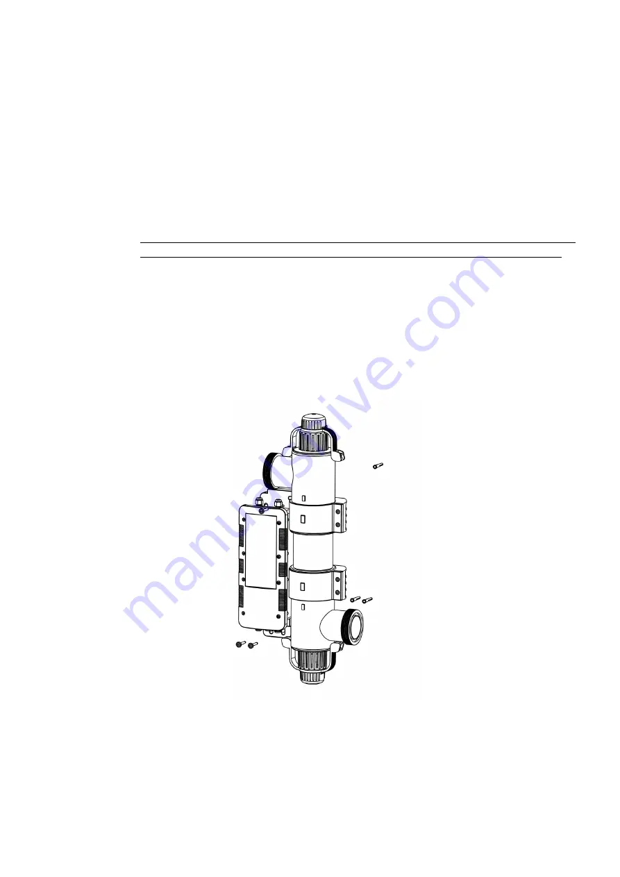
See Fig. 3 for mounting instructions when securing to the wall or floor. 


Fig.3


3.2  Pipe work 


The device should be placed downstream (after) of any pumps, filters and heating devices but upstream 
(before) of any chemical dosing or similar water treatment (see Figs. 4 and 5). 

Summary of Contents for HR-30-B

Page 1: ...MINI H R UV C STANDARD Installation Operating Manual HR 30 B ENGLISH...

Page 2: ...work 5 3 3 Flow direction 6 3 4 Connection 7 3 6 Electrical connection 8 4 OPERATING INSTRUCTIONS 9 4 1 Flow requirements 9 4 2 Water quality 9 5 MAINTENANCE 9 5 1 Essential parts to carry out annual...

Page 3: ...ed Power must be supplied through a Residual Current Device RCD with a rated residual operating current not exceeding 30mA Do not run this unit dry Do not cover this unit The unit must not be submerge...

Page 4: ...4 Fig 1 Dimensions Fig 2...

Page 5: ...alling vertically the 1m clearance space must be above or below the unit if installing horizontally the 1m clearance space must be to the left or right of the unit WARNING The device must be installed...

Page 6: ...6 Fig 4 3 3 Flow direction The device is factory set to accept input water flow entering on the left and exiting on the right...

Page 7: ...unit is supplied with unions to allow connection to 2 or 63 mm rigid pipe Reducers are also supplied to allow connection to 50 mm or 1 rigid pipe see Fig 7 For pipework 63 mm or 2 in diameter For pipe...

Page 8: ...lation may result in serious damage to property persons The device must be installed in accordance with the country regional requirements and regulations and an Electrical Installation Certificate mus...

Page 9: ...otal Dissolved Solids TDS Calcium hardness 200 1 000 ppm WARNING Failure to meet the water quality limits will void the warranty Upon completion of the installation run the water circulating pump to p...

Page 10: ...lamp and quartz sleeve Unscrew all the highlighted fasteners Unclamping the clip from body 1 Pull the clip in shown direction to unlock from body 2 Pull the second side after unlocking the 1st side R...

Page 11: ...leeve can be removed Slide the O ring off the quartz sleeve The quartz sleeve can now be removed Cleaning the quartz sleeve Clean the sleeve and polish with a soft cloth or paper towel If you live in...

Page 12: ...ttings have been manufactured from polymers that have been specifically stabilised to protect them from the effects of the UVC emitted from the UV lamps Despite this UV protection they will be eroded...

Page 13: ...y for inspection Proof of purchase may be required The manufacturer will not be liable in cases of incorrect installation of the product inappropriate use or neglect Any damages occurred due to shippi...

Page 14: ...14 Notes...

Page 15: ...ertfordshire SG1 2BH United Kingdom __________________________________________________________________________________ Customer Information ATTACH TO THE PRODUCT Company Name Contact Name Daytime Tele...

Page 16: ...16 Unit 11 Gunnels Wood Park Stevenage Herts SG1 2BH Sales elecro co uk www elecro co uk 44 0 1438 749474 Copyright MANE61 EN MINI H R UV C STANDARD Manual V1 15 07 2021 Elecro...

Reviews: