14
On the
top
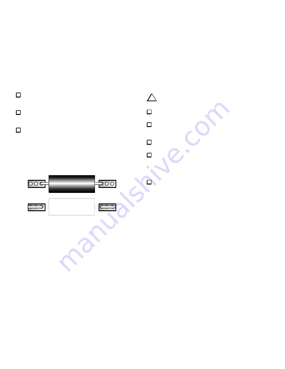
side of the board, locate the component outline for .005-
ohm current-sensing resistor R7 (near the DC power connector, J3). Each
of R7's pads has three holes.
Bend the leads of the .005-ohm, 3-watt resistor to match the spacing
between R7s innermost pair of holes (see Figure 2a). Install the resistor,
pressing it down onto the board as far as it will go.
On the bottom side, fold R7's leads outward so they lay flat against
the pads (Figure 2b). Trim the leads to match the size of the pads. Solder
each lead over the full length of the pad.
Note:
Components may be soldered one at a time or in groups. Leads can
be trimmed either before or after soldering.
Flush trimming
(trimming
very close to the board) is required only when specified. Otherwise, trim
leads to about 1/16" [1.5 mm] or less in length.
(a)
(b)
Figure 2
i
The leads on small capacitors are fragile. Do not pull on the
leads or bend them excessively.
Sort all capacitors into groups by capacitance value. Start by
grouping them by physical appearance (size, color, etc.).
In all cases where two or more capacitor types have the same value,
further sort them by lead spacing and voltage rating. The parts list
provides identification details for specific capacitor types.
Locate an
0.1- µF
("104") capacitor with
0.1" lead spacing
for use
at C75.
Install C75 at its indicated location on the
bottom
of the board, near
the back edge. The capacitor must be seated as close to the board as
possible, with 1/16" (3 mm) or less lead length exposed. Remove any U-
shaped bends or folds using long-nose pliers. Solder C75 from the top
side of the board.
Install a
.01-µF
("103") capacitor with
0.1" lead spacing
at C65.
C65 is located on the
bottom
side of the board, near the front edge. Keep
the lead length short, as described in the previous step.


