ELECPS
ELECPS
-
-
8XS
8XS
-
-
EU
EU
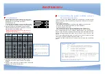
1. If the Satellite unit is used with a Master unit, connect the
supplied RJ45 link-up cable to one of the xBus connector of
the 8XM and to one of the xBus connector of
the ELECPS-8XS-EU.
To cascade several Satellites, link the second xBus connec-
tor of a Satellite with the xBus connector of the next Satellite.
2
3 4
DC
DRY CONTAC TS
MAX 24VDC - 20mA
12VDC AUX
POWER SUPPLY
I/O
A 1 2
3 4
10/100
Link
10 0
RS232
x Bus
Term
S B 5
6 7 8
1
RS232
Slct
Term
8
6
7
x Bus
3 4
5
Power
2
B 1
A
RS232
Slct
Term
8
6
7
x Bus
3 4
5
Power
2
B 1
A
2. Allocate an address to each Satellite by positioning the
address selection DIP-switches marked "Slct" on the front
panel according to the following table.
- Unplug the power cords of the ELECPS-8XS-EU before
changing its DIP switches.
- Do NOT use the same address for two different Satellites.
Position Off = switch upwards,
Position On = switch downwards
DIP-Switch 1 is located on the left
side
DIP-Switch 5 and 6 are used to
activate the built in termination
resistors.
[ON]
[ON]
[ON]
[ON]
16
[ON]
[ON]
[ON]
Off
15
[ON]
[ON]
Off
[ON]
14
[ON]
[ON]
Off
Off
13
[ON]
Off
[ON]
[ON]
12
[ON]
Off
[ON]
Off
11
[ON]
Off
Off
[ON]
10
[ON]
Off
Off
Off
9
Off
[ON]
[ON]
[ON]
8
Off
[ON]
[ON]
Off
7
Off
[ON]
Off
[ON]
6
Off
[ON]
Off
Off
5
Off
Off
[ON]
[ON]
4
Off
Off
[ON]
Off
3
Off
Off
Off
[ON]
2
Off
Off
Off
Off
1
DIP-Switch
4
DIP-Switch
3
DIP-Switch
2
DIP-Switch
1
Satellite
Adress
3. On both devices located at the end of the xBus, switch
the DIP-Switch 5 and 6 to ON to activate the termination
resistors.
4. Plug the 2 power cables into 2 grounded sockets. The A and B
LEDs light on to confirm that power is on.
2. Controlling the power outlets using a
Terminal connection
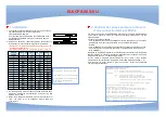
The power outlets of the ELECPS-8XS-EU can be individually controlled and the
status of each power outlet can be read out using a simple ASCII protocol through a
serial connection.
The connection can be done:
- using the RS232 port (SubD-9F connector marked RS232 on the front panel).
In this case, use the supplied serial cable to connect the EPS to
an available serial port of your PC.
- using the RS485 port (RJ45 connector marked xBus on the front panel). In
this case, you have to make a special serial cable (see user guide on the CD).
Run a terminal program such as Windows HyperTerminal or the MicroTerminal
program on the CD (folder miscellaneous) and configure the appropriate serial port
with the following settings: 9.600 bauds, 8 bits, no parity, 1 stop bit and no flow
control.
If you use the MicroTerminal program on the CD you only have to choose the used
serial port, this program is already configured at 9600, n, 8, 1.
To control the power outlets from your computer, enter the command as explained
below:
Syntax of the Command : Pxy=z
Parameter
Value
Function
x
1 to 16
Means the corresponding connected Satellite address
y
0
Means that all the sockets have to be controlled together
1 to 8
Indicates the number of the socket you want to control
z
0
Command to switch the socket(s) OFF
1
Command to switch the socket(s) ON
r
Command to restart the socket(s)
t
Command to toggle the state of the socket
Example to control the Satellite with address 1
Example to control the satellite with address 2
=> DIP-Switch: 1, 2, 3 and 4 = Off
DIP-Switch: 1 = on, DIP-Switch: 2, 3 and 4 = off
P10=1 <ENTER> switch all 8 sockets ON
P20=1 <ENTER> switch all 8 outlets ON
P10=0 <ENTER> switch all 8 sockets OFF
P25=0 <ENTER> switch outlet 5 OFF
P14=r <ENTER> restart socket 4
P18=t <ENTER> toggle socket 8
The 8XS accepts lower case and upper case commands.
The 8XS sends the command back as an echo.
1. Installation


