background image

SoilTest PRO Auto Soils Consolidator (ASC) 

25-0500  


Original Instructions 

9901X0275 Issue 2 


OPERATING INSTRUCTIONS 


SoilTest PRO Auto Soils Consolidator (ASC) 


25-0500 


ELE International 

Chartmoor Road, Chartwell Business Park 

Leighton Buzzard, Bedfordshire, LU7 4WG 

England 

phone: +44 (0) 1525 249200 

fax: +44 (0) 1525 249249 

email: [email protected]   

http://www.ele.com 

ELE International, a division of Hach Lange Ltd.


Distributor: 


ELE International 

Soiltest Product Division 

PO Box 389, 5600 Lindbergh Drive 

Loveland, CO 80539  

USA


phone: +1 (970) 663 9780 

fax: +1 (970) 663 9781   

email: [email protected] 

http://www.eleusa.com 


In the interests of improving and updating its equipment, ELE reserves the right to alter specifications to equipment at any time.  

ELE International 2019 


Summary of Contents for SoilTest PRO

Page 1: ... 44 0 1525 249200 fax 44 0 1525 249249 email ele eleint co uk http www ele com ELE International a division of Hach Lange Ltd Distributor ELE International Soiltest Product Division PO Box 389 5600 Lindbergh Drive Loveland CO 80539 USA phone 1 970 663 9780 fax 1 970 663 9781 email soiltest eleusa com http www eleusa com In the interests of improving and updating its equipment ELE reserves the righ...

Page 2: ... 1 Consolidation Cell Range 9 4 Installation 10 4 1 Moving Lifting and Siting 10 4 2 Safety 10 4 3 Electrical Safety 11 4 3 1 Portable Appliance Tests PAT 11 4 4 Mounting the Load Cell and LVDT 12 4 5 Installation Checks 13 5 Operation 14 Appendix 1 Direct Connection to the ASC Point to Point PC Configuration 24 Appendix 2 USB Port for Firmware Update 27 Appendix 3 Troubleshooting Guide 28 Appendi...

Page 3: ...t permitted under applicable law The user is solely responsible to identify critical application risks and install appropriate mechanisms to protect processes during a possible equipment malfunction Please read this entire manual before unpacking setting up or operating this equipment Pay attention to all danger and caution statements Failure to do so could result in serious injury to the operator...

Page 4: ...t 3 3 Limits Limitation of voltage changes voltage fluctuations and flicker in public low voltage supply systems for equipment with rated current 16A per phase and not subject to conditional connection EN55032 2012 Electromagnetic compatibility of Multimedia Equipment Emission Requirements Class A Emissions 1 4 Other Certification Canadian Radio Interference Causing Equipment Regulation IECS 003 C...

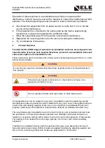
Page 5: ...e format 1944 X XXXXX WARNING Do not test any specimen material other than those explicitly listed in the Specifications of this manual WARNING Personal injury hazard Instruments or components are heavy Use assistance to install or move DANGER Do not operate machine near open flame or other heat sources Compressible soils can be subject to long term consolidation under the loads imposed by foundat...

Page 6: ...ata logging reporting and automatic analysis is provided through ELE s DS8 software application 2 1 ASC Customer Benefits Fully automatic reduces testing time Compact footprint saves laboratory space Saves configurations for easy set up of multiple cells and repeat tests Controls up to 16 Auto Soils Consolidator machines from one PC improves laboratory efficiency client network dependent Ability t...

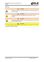
Page 7: ...ng the machine s electrical circuitry WARNING Inappropriate use of the consolidation frame could result in a risk of crushing WARNING Test sample cells being loaded on the consolidation frame present a pinch point if handled incorrectly CAUTION It is recommended that appropriate PPE safety footwear and eye protection be worn whilst operating consolidation machines ...

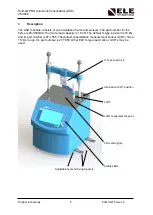
Page 8: ... is 25 0500 09 The frame load capacity is 15 kN The default S type load cell is 15 kN and its part number is 27 1565 The default consolidation measurement sensor LVDT has a 15 mm range It s part number is 27 1650 Other ELE S type load cells or LVDTs may be used S Type Load Cell Alternative LVDT position LVDT LVDT measurement point Cell centring pip Status LEDs Adjustable feet and fixing brackets ...

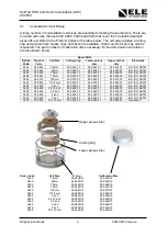
Page 9: ...25 0467 75 mm 25 0467 12 25 0469 11 25 0503 10 BS ISO ASTM 0520 25 0510 100 mm 25 0510 12 25 0520 11 25 0510 10 BS ISO ASTM 0520 25 0520 112 8 mm 25 0520 12 25 0520 11 25 0520 10 BS ISO ASTM 0490 25 0499 2 inch 25 0499 12 25 0490 11 25 0499 10 BS ISO ASTM 0490 25 0489 2 416 inch 25 0489 12 25 0490 11 25 0489 10 BS ISO ASTM 0490 25 0490 2 5 inch 25 0490 12 25 0490 11 25 0479 10 BS ISO ASTM 0469 25 ...

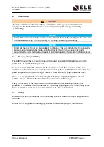
Page 10: ... the fixing brackets and suitable screws otherwise the brackets can be rotated out of the way Lastly the levelling of the machine should be checked with a suitable spirit level not provided If necessary the machine can be levelled by adjusting the feet height using a flat blade screwdriver and 12 mm spanner 1 2 wrench also not provided 4 2 Safety Whilst the test is in operation do not remove any c...

Page 11: ...Tests PAT All ELE designed products are tested for electrical safety prior to sale An electrical safety test label is fitted usually adjacent to the mains input socket Should no label be found please contact ELE s Service Department quoting the serial number of the equipment Organisations have an obligation to ensure equipment is maintained and is safe for use Regular PAT testing is one means of e...

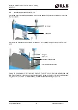
Page 12: ...d M16 bolt Load Cell The LVDT is mounted to the base of the load cell see below using the load pin and LVDT arm Load pin LVDT arm M5 socket head screw LVDT measurement seat Use a 24 mm spanner 15 16 wrench to attach the LVDT arm to the load cell with the load pin Insert the LVDT into the arm and tighten the M5 screw to retain it The height adjustment may be completed later see Motor Drive and Home...

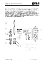
Page 13: ... transducer must connect to the next DIN connector item 5 sensor input 2 Any further displacement sensors associated with manual consolidation arms connect to the manual sensor inputs item 6 sensor inputs 3 and 4 The AC power connector is an IEC C14 fused filtered appliance switch item 7 The supply voltage should be 100 to 240 V AC at 50 60 Hz The dual pole switch contains two fuses rated at 1A T ...

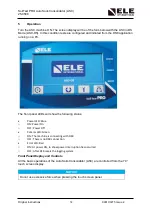
Page 14: ...ont panel LEDs will show the following status Power LED Blue o ON Power On o OFF Power Off Comms LED Green o ON The machine is connecting with DS8 o OFF There is no DS8 connection Error LED Red o ON At power ON to show power interruption has occurred o OFF After DS8 resets the logging system Front Panel Display and Controls All the basic operations of the Auto Soils Consolidator ASC are controlled...

Page 15: ... the operation of the system Test Start Menu Software Update Menu Tools Settings Menu Calibration Menu Test Start Menu This menu screen allows the user to View the status of test Stop a test Adjust the frame position Tools Settings Menu This menu screen allows the user to Change the language and measurement units View or adjust comms port settings Adjust the date time and display brightness Calibr...

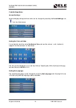
Page 16: ...tial screen Setting the Time and Date To set the date and time select Set Date Time and use the various and buttons to adjust to the format shown on the screen The time can be displayed in 12 or 24 hour format Selecting the US format box will change the date format to MM DD YYYY Setting the Language The operating language can be changed by selecting Set Language and choosing from one of the pre pr...

Page 17: ...r sample dimensions sample weight and sample density The following table shows the available section Units Load Dimensions Weight Density Stress SI kN mm g kg m kPa US Imperial lbf inch lb lbf ft psi Metric kgf cm g g cm kgs cm2 The default setting for the display units is S I To change this press Set Units and select the required units Display Version The Display Version will show the current ver...

Page 18: ...ition During this process the display will show the Status of the machine as Unloading A pop up message will then show when the machine reaches its Top Limit and then returns to the HOME position Wait until the machine status shows it is at the HOME position With the cell containing a stiff soil or its calibration block confirm there is sufficient headroom for the cell to be inserted or removed fr...

Page 19: ...e DS8 application it is useful to use default calibration values for the 15 kN and 15 mm sensors This will be used to give an indication of the system status Select the Calibration icon enter the passcode the default passcode is 937707 and Calibrate In turn select ASC Sensor 1 and 2 For ASC Sensor 1 and 2 select the DEFAULT option and confirm The parameters can then be viewed Sensor Gain Slope Ran...

Page 20: ...Menu in the Diagnostics Miscellaneous Network Set up section Using the up and down arrows select the parameter to be changed then select the Edit button Change the ASC machine number to that required Change the Network address parameter and then the Enter key to store these values Exiting via the Home key will leave the Network address values unchanged The ASC has an RS 232 serial port for diagnos...

Page 21: ...e if a malfunction is detected If an error is detected a dialogue box with the error code will be displayed If the error has resulted in the machine being shut down and unable to operate further this error must be fixed and cleared before the operation can continue See Appendices for a list of error codes and their meanings If the error persists or further assistance is required contact the ELE se...

Page 22: ...frame is not in this state press the frame up key The machine will return to its top limit and then return to its HOME position Then with the cell in place press the frame down key until the frame reaches it s START position Adjust the LVDT measurement seat so the tip of the LVDT has definite contact if this is not already the case Lock the LVDT seat in place with its lower knurled nut The machine...

Page 23: ...tion of force displacement transducers Service Spares and Accessories It is recommended that either the ELE Service Department or an authorised distributor be contacted for details of available spare parts or servicing requirements Full part numbers for the spares used on cells are detailed in a previous section Consolidation Cell Range Other spares accessories include 82 2500 Water bottle 500 ml ...

Page 24: ... following actions Make an RJ45 Ethernet connection between the PC and the ASC Access the Control Panel of the PC Follow the instructions below the screen shots are taken from a Windows 7 PC This same process on a Windows 10 PC is similar but will have a different screen appearance Select Network and Sharing Centre Select the LAN Connection option If none is shown check that the Ethernet cable bet...

Page 25: ...SoilTest PRO Auto Soils Consolidator ASC 25 0500 Original Instructions 25 9901X0275 Issue 2 Select Properties Select Properties for Internet Protocol Version 4 TCP IPv4 ...

Page 26: ...e Host Name that will be ELE ASC01 as a default This should be changed when multiple ASCs are on the network and is accessed via the Diagnostics Miscellaneous Network Set up menu The ASC number can be changed from 1 to 99 to modify the Host Name from ELE ASC01 to ELE ASC99 Configuring the Ethernet Comms Ensure a connection has been made between the Ethernet port on the ASC and the network router o...

Page 27: ... The root directory of the ASC will contain a file called Image BIN this is the firmware file In order to update the firmware file take a copy of the existing file and save it to another location Copy and paste the updated firmware file into the root directory of the ASC selecting Copy and Replace when prompted After updating the firmware safely remove the device from the PC using the Eject functi...

Page 28: ...htness set too low Adjust brightness Internal cables loose Refer to ELE Customer Service Machine not operating Frame travel on limit Check cross head set up LVDT sensor over range Check sensor position Load cell over range Check frame Machine not reaching START position Frame cross head too low Move the cross head up level and secure Test stopping due to LVDT overload LVDT not adjusted correctly M...

Page 29: ...s 29 9901X0275 Issue 2 Appendix 4 Glossary of Icons and Menu Tree Home Test Start Software Update Menu Accept Enter Calibration Protected Area Tools Settings Menu Test Stop Edit USB Connection Scroll Left Scroll Right Warning Scroll Up or Unload Scroll Down or Load Reset ...

Page 30: ...ay Motor Status Test Calibration Calibrate Sensors View Clear Default Diagnostics Miscellaneous Network Setup Autocycle Test Service Functions New Passcode Set Serial Number Reload Defaults Software Update SD Format Auto Update Software Update USB Link Tools Settings General Settings Set Date Time Set Language Set Units Display Version User Defined Settings Comms Port Settings Adjust Display Motor...

Page 31: ...g policy 17 LFN working buffer could not be allocated 18 Number of open files _FS_SHARE 19 Given parameter is invalid 25 SD card is not present 26 SD card error generic 27 SD card full 28 Not applicable 29 Invalid filename specified 30 Specified number of bytes were not written to SD card 31 File too big to load into internal buffer 32 File size is 0 33 Error closing file on SD card 34 Error readi...

Page 32: ...Not applicable 60 Log is corrupt 61 Error setting real time clock 62 Not applicable 63 Not applicable 64 Touch screen controller fault 65 Not applicable 66 Not applicable 67 Not applicable 68 Not applicable 69 Not applicable 70 Not applicable 71 Not applicable 72 Not applicable 73 Not applicable 74 Not applicable 75 Not applicable 76 Not applicable 77 Not applicable 78 Not applicable 79 Not applic...

Page 33: ... firmware logger mismatch 110 Invalid number of command parameters firmware logger mismatch 111 Generic busy error e g result files being scanned file being saved etc 200 Operation OK 201 Command response received but CRC check failed 202 Data block sent received CRC check failed 203 Command response timeout 204 Data timeout 205 Transmit FIFO underrun 206 Receive FIFO overrun 207 Start bit not det...

Page 34: ...space was erased 224 Command has been executed without using internal ECC 225 Erase sequence cleared before executing 226 Error in sequence of authentication 227 Invalid voltage range 228 Address out of range 229 Switch error 230 SDIO disabled 231 SDIO function busy 232 SDIO function failed 233 SDIO unknown function 234 Internal error 235 Not configured 236 Request pending 237 Request not applicab...

Page 35: ...artwell Business Park Leighton Buzzard Bedfordshire LU7 4WG UK declare under our sole responsibility that the following equipment Product ASC Range Catalogue Number 25 0500 09 Description Automatic consolidation frame for soil sample testing The object of the declaration described above is in conformity with the relevant Union Harmonisation Decision and the provisions of the following standard s o...

Page 36: ...omplies with Part 15 of the FCC Rules Operation is subject to the following two conditions 1 This device may not cause harmful interference and 2 this device must accept any interference received including interference that may cause undesired operation TEST REPORT INFORMATION dB Technology TR R000637_V00 RESPONSIBLE PARTY IN USA NAME ELE International Inc ADDRESS PO Box 389 5600 Lindbergh Drive L...

Page 37: ...Original Instructions 37 9901X0275 Issue 2 DIRECTIVE ON WASTE ELECTRICAL ELECTRONIC EQUIPMENT WEEE ...

Page 38: ...Original Instructions 38 9901X0275 Issue 2 ...

Reviews: