Version: 2004/08/16
Order No.: 9526
© ELCON Systemtechnik GmbH http://www.elcon-system.de
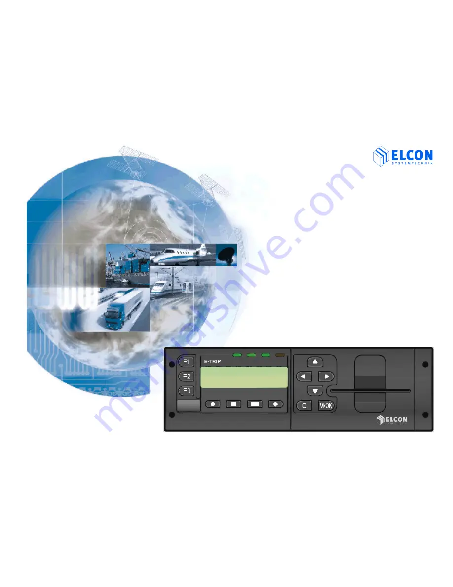
E
-
T
R
I
P
®
Onboard Computer
for Fleet Management
Mounting Guidelines
Page 1: ...Version 2004 08 16 Order No 9526 ELCON Systemtechnik GmbH http www elcon system de E E T TR RI IP P Onboard Computer for Fleet Management Mounting Guidelines...
Page 2: ...pe of supply E TRIP Version 2004 08 16 Order No 9526 Page 2 1 E TRIP Onboard Unit 2 E TRIP Operating Manual 3 Cable set 4 Built in frame 5 Clamps 6 PSRR antenna 7 GPS antenna 8 GSM antenna 9 Driver ca...
Page 3: ...AE J1708 Interface 11 3 4 2 Digital Input 11 3 4 3 Digital Output 12 3 4 4 Temperature sensor 13 3 4 5 NMEA interface 13 3 4 6 Auxiliary Serial Port 13 3 5 Installation of the Onboard Unit 14 3 6 SIM...
Page 4: ...ons E TRIP is a manipulation safe unit You are able to analyze the fuel economy of your vehicle s fleet while the driver can check the vehicle s operating data E TRIP has been designed as a modular un...
Page 5: ...of the GPS Global Positioning System satellite signals for vehicle s positioning either upon request or at adjustable intervals PSRR Private Short Range Radio The automatic data transfer between the...
Page 6: ...ntee that interference will not occur in a particular installation If this equipment does cause harmful interference to radio or television reception which can be determined by turning the equipment o...
Page 7: ...individual requirements Please ask your dealer for more information The detailed description of the installation is given in a separate document This document is available from your vendor or service...
Page 8: ...8 3 2 Maintenance To clean the unit s front panel use a clean cloth only It should be soft dust laying and antistatic Don t apply any cleaning agents in order to prevent the surface from being damaged...
Page 9: ...TEMP_Sens_A C1 DIGI_IN_1 B1 Speed Pulse A1 Battery D2 TEMP_Sens_B C2 DIGI_IN_2 B2 A2 Light D3 NMEA_TxD C3 DIGI_IN_3 B3 A3 Ignition D4 GND C4 DIGI_IN_4 B4 RPM A4 D5 AUX_SER_TxD C5 ALARM_A B5 A5 GND D6...
Page 10: ...sensor B6 SAE_J1708_A SAE J1708 Interface Line A B7 SAE_J1708_GND SAE J1708 Interface GND B8 SAE_J1708_B SAE J1708 Interface Line B B6 B8 see subchapter 3 4 1 Chamber C C1 DIGI_IN_1 Input 9V 36V DC C1...
Page 11: ...help of the PC program E TRIP Service Tool it is possible to determine which input of the Onboard Unit shall be used 3 4 2 Digital Input The digital inputs allow to have below functions recorded by th...
Page 12: ...ssary to enter a PIN upon setting the specific vehicle data set under E TRIP Master Recommendation to the workshop personnel The workshop card offers to select from the onboard unit menu the function...
Page 13: ...ed via output D3 D4 of the Onboard Unit in a way that the current vehicle position is transmitted via this interface In addition to the output D3 D4 the vehicle position is also sent out via the servi...
Page 14: ...ttery Observe the safety instructions from the respective car manufacturer Note that upon disconnecting devices with volatile memory will lose their information Therefore it is necessary before discon...
Page 15: ...lding frame in the dashboard Note Before installation of the holding frame pull cable trunks through the holding frame After proper installation of the holding frame in the dashboard turn the respecti...
Page 16: ...na cables blue for GPS violet for GSM fawn for PSRR until they noticeably snap in Connect the cable trunks with the four plugs of different colours to the device until they noticeably snap in A white...
Page 17: ...sure you have got a plug in SIM card Insert the SIM card into the provided SIM card holder see figure 5 figure 5 After this insert the SIM card holder into the Onboard Unit as shown in figure 6 until...
Page 18: ...four designated fixing points see A figure 7 After this fasten the battery with the provided holding angle figure 7 3 When laying the cables take care not to jam or cut off the cable by moving parts...
Page 19: ...ular connector of the Orbcomm Modems figure 7 PWR BAT and the battery with the modem 3 7 1LED Codes of Stella ST 2500 L1 LED While the unit is searching the satellite downlink L1 flashes in red Once a...
Page 20: ...acknowledged by pressing the button M OK After selecting the function Adjustment for setting the RTC at first you shall enter the time When doing so pay attention not to enter the local time but GMT G...
Page 21: ...ECHNOLOGIES Canada 115 Midpark Road Unit 1 London ON N6N 1B2 Phone 001 519 681 2700 Fax 001 519 681 3782 Mail a v c bellnet c Kelland International Ltd China Beijing 100020 Room 1512B No 22 Chao wai S...
Page 22: ...aLog GmbH Germany D 21394 Westergellersen Drosselweg 4 Phone 49 0 41 35 80 07 97 Fax 49 0 41 35 80 07 37 Mail info BaTaLog de GESTECH 2001 Canada 478 St Hubert Laval Qu bec H7G 2Y9 Phone 001 450 629 2...
Page 23: ...E TRIP Version 2004 08 16 Order No 9526...
Page 24: ...E TRIP Version 2004 08 16 Order No 9526 D 09232 Hartmanndorf Obere Hauptstrasse 10 Germany www elcon system de...