


10
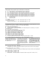
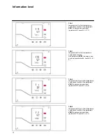
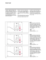
In addition, the Info sequence shows
the total heat gain (ERT), the daily heat
gain (ERTd) and the speed of pumps
P1.. P3 (ED1..ED3).
It is preferable to use a volume flow
sensor for the total or daily heat gain
calculation. Parameter VSA = 1 or 2
(E3-4.3) confirms that a volume flow
sensor is being used. The heat gain
display is enabled when confirmation is
received that a volume flow sensor is
present.
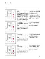
If no volume flow sensor is present,
heat gain values can only be displa-
yed if the minimum lower set point
for the heat transfer pump is set to
100 percent.
In this situation the heat
gains are calculated on the basis of the
default liquid flow rate.
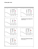
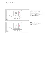
ERT total heat gain in kWh; range: 0 .. 199999 kWh
Total heat gain can be reset to zero by pressing and holding the [-] key for five seconds while a value is being displayed.
ERTd daily heat gain in kWh; range: 0 .. 999 kWh
The day's heat gain can be reset to zero by pressing and holding the [-] key for five seconds while a value is being displayed.
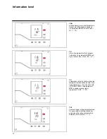
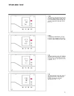
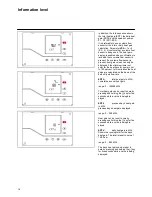
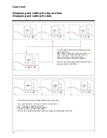
ED1 speed of pump P1 in %, range 30 .. 100 %
ED2 speed of pump P2 in %, range 30 .. 100 %
ED3 speed of pump P3 in %, range 30 .. 100 %
The speeds (ED1 … ED3) are only displayed if the respective minimum set point (USW1.. USW3) is < 100 %.
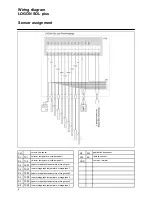
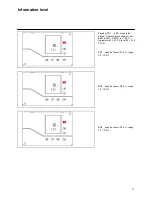
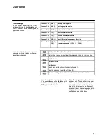
Default assignment for measurement inputs (vary with system circuit schematic):
S1
TC1 collector temperature or collector temperature sensor for collector panel 1
S2
TC2 collector temperature or collector temperature sensor for collector panel 2
S3
TSP1 upper storage tank temperature or upper storage tank temperature sensor for storage tank 1
S4
TSR1 lower storage tank temperature or lower storage tank temperature sensor for storage tank 1
S5
TSP2 upper storage tank temperature or upper storage tank temperature sensor for storage tank 2
S6
TSR2 lower storage tank temperature or lower storage tank temperature sensor for storage tank 2
S7
TSP3 upper storage tank temperature or upper storage tank temperature sensor for storage tank 3
S8
TSR3 lower storage tank temperature or lower storage tank temperature sensor for storage tank 3
S9
application dependent
S10
application
dependent
collector sensor:
temperature measuring range: -20° .. 150°C, rated temperature range: -20° .. 250°C
storage tank/return-line sensor:
temperature measuring range: -20° .. 150°C, rated temperature range: -20° .. 90°C
The following measured values can be assigned to any measured value input depending on the system configuration or on the acti-
vated functions. The measured values - if activated - can be checked using the
Info key.
TRH backup heater return-line temperature
TR
return-line temperature for heat gain calculation
TX
comparative value for heater return-line temperature when backup heating function is activated (e.g., in conjunction
with VISTRON V750 LC.
TW
heat exchanger or bypass temperature:
TWW temperature of the first storage tank for hot water destratification
TH1 temperature
measurement
for
first thermostat function:
TH2 temperature measurement for second thermostat function:
TVA1 temperature A for first temperature comparison function:
TVB1 temperature B for first temperature comparison function:
TVA2 temperature A for second temperature comparison function:
TVB2 temperature B for second temperature comparison function:
SE
solar sensor to measure impinging solar radiation in W/m2:
VM
volume flow measurement or volume flow sensor (GND, VM), measuring range: 50 .. 1500 l/h
VM
Volumenstrom-Messwert bzw. Volumenstromsensor (GND, VM), Messbereich: 50 .. 1500 l/h
Summary of Contents for LOGON SOL plus
Page 22: ...Notes...
Page 23: ...Notes...