


ELM-96BP-LON
instruction manual
IM447-U v0.67
pag. 15
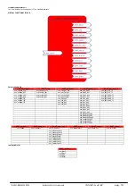
Output variable list
Type
Name
Content
SNVT_volt_ac nvo_3phase_volt
3-PHASE SYSTEM VOLTAGE [V]
SNVT_volt_ ac
nvo_voltage_ph1
PHASE VOLTAGE L1-N [V]
SNVT_volt_ ac
nvo_voltage_ph2
PHASE VOLTAGE L2-N [V]
SNVT_volt_ ac
nvo_voltage_ph3
PHASE VOLTAGE L3-N [V]
SNVT_volt_ ac
nvo_voltage_l12
LINE VOLTAGE L1-2 [V]
SNVT_volt_ ac
nvo_voltage_l23
LINE VOLTAGE L2-3 [V]
SNVT_volt_ ac
nvo_voltage_l31
LINE VOLTAGE L3-1 [V]
SNVT_amp
nvo_3phase_curr
3-PHASE SYSTEM CURRENT [A]
SNVT_amp
nvo_current_ph1
LINE CURRENT L1 [A]
SNVT_amp
nvo_current_ph2
LINE CURRENT L2 [A]
SNVT_amp
nvo_current_ph3
LINE CURRENT L3 [A]
SNVT_pwr_fact
nvo_3ph_pwr_fac
3-PHASE SYS. POWER FACTOR [-]
SNVT_pwr_fact
nvo_pwr_fac_ph1
POWER FACTOR L1 [-]
SNVT_pwr_fact
nvo_pwr_fac_ph2
POWER FACTOR L2 [-]
SNVT_pwr_fact
nvo_pwr_fac_ph3
POWER FACTOR L3 [-]
SNVT_power_f
nvo_3ph_Apwr
3-PHASE S. APPARENT POWER [kVA]
SNVT_power_f
nvo_Apwr_ph1
APPARENT POWER L1 [kVA]
SNVT_power_f
nvo_Apwr_ph2
APPARENT POWER L2 [kVA]
SNVT_power_f
nvo_Apwr_ph3
APPARENT POWER L3 [kVA]
SNVT_power_f
nvo_3ph_pwr
3-PHASE SYS. ACTIVE POWER [kW]
SNVT_power_f
nvo_pwr_ph1
ACTIVE POWER L1 [kW]
SNVT_power_f
nvo_pwr_ph2
ACTIVE POWER L2 [kW]
SNVT_power_f
nvo_pwr_ph3
ACTIVE POWER L3 [kW]
SNVT_power_f
nvo_3ph_Rpwr
3-PHASE S. REACTIVE POWER [kVAr]
SNVT_power_f
nvo_Rpwr_ph1
REACTIVE POWER L1 [kVAr]
SNVT_power_f
nvo_Rpwr_ph2
REACTIVE POWER L2 [kVAr]
SNVT_power_f
nvo_Rpwr_ph3
REACTIVE POWER L3 [kVAr]
SNVT_elec_kwh_l
nvo_3ph_Wh_T1
3-PHASE SYS. ACTIVE ENERGY T1 [kWh]
SNVT_elec_kwh_l
nvo_3ph_RVAh_T1
3-PHASE S. REACTIVE ENERGY T1 [kVArh]
SNVT_elec_kwh_l
nvo_3ph_Wh_T2
3-PHASE SYS. ACTIVE ENERGY T2 [kWh]
SNVT_elec_kwh_l
nvo_3ph_RVAh_T2
3-PHASE S. REACTIVE ENERGY T2 [kVArh]
SNVT_freq_hz
nvo_Frequency
FREQUENCY [Hz]
SNVT_amp_mil
nvo_N_Current
NEUTRAL CURRENT [A]
SNVT_elec_kwh_l
nvo_3ph_AVAh_T1
3-PHASE S. APPARENT ENERGY T1 [kVAh]
SNVT_elec_kwh_l
nvo_3ph_AVAh_T2
3-PHASE S. APPARENT ENERGY T1 [kVAh]
SNVT_temp
nvo_temperature
TEMPERATURE [°C]
SNVT_count
nvo_hours_cnt
HOURS COUNTER [h]
SNVT_amp_mil
nvo_MaxAvgCurrL1
MAX AVG CURRENT L1 [A]
SNVT_amp_mil
nvo_MaxAvgCurrL2
MAX AVG CURRENT L2 [A]
SNVT_amp_mil
nvo_MaxAvgCurrL3
MAX AVG CURRENT L3 [A]
SNVT_power_f
nvo_MaxAvg3PhAP
MAX AVG 3-PH. ACTIVE POWER [kW]
SNVT_power_f
nvo_MaxAvg3PhRP
MAX AVG 3-PH. REACTIVE POWER [kVAr]
SNVT_power_f nvo_MaxAvg3PhApP
MAX AVG 3-PH. APPARENT POWER [kVA]
SNVT_power_f nvo_LastAv3PhAcP
LAST AVERAGE 3-PHASE ACTIVE POWER [kW]
SNVT_power_f
nvo_LastAv3PhRP
LAST AVERAGE 3-PHASE REACTIVE POWER [kVAr]
SNVT_power_f nvo_LastAv3PhApP
LAST
AVERAGE 3-PHASE APPARENT POWER [kVA]
SNVT_amp_mil
nvo_MaxAvCurrN
MAX AVG CURRENT NEUTRAL [A]
SNVT_amp_mil
nvo_LastAvCurrN
LAST AVERAGE CURRENT NEUTRAL [A]
SNVT_amp_mil
nvo_LastAvCurrL1
LAST AVERAGE CURRENT L1 [A]
SNVT_amp_mil
nvo_LastAvCurrL2
LAST AVERAGE CURRENT L2 [A]
SNVT_amp_mil
nvo_LastAvCurrL3
LAST AVERAGE CURRENT L3 [A]
SNVT_state nvo_IO_State DIGITAL OUTPUT DO1, DO2,
Input variable list
Type
Name
Content
SNVT_switch nvi_Out1
DIGITAL
OUTPUT DO1 CONTROL REGISTER
SNVT_switch nvi_Out2
DIGITAL
OUTPUT DO2 CONTROL REGISTER
SNVT_switch nvi_REC
RESET ENERGY COUNTERS
SNVT_switch
nvi_RMA
RESET MAX AVG (max demand) VALUES
NOTE
(*)
The
nvo_IO_State
is a 16 bit variable. The bit have the following meaning:
•
Bit 0
DO1 state
•
Bit 1
DO2 state
•
Bit 2
Input state
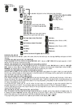
Service Led
: If the “decommission” instrument will be connected to a LON network, the
Service Led
must have a regular blink (the time with Led ON it’s similar to the time with
Led OFF). After the “commission” operation, during the normal functioning, the Led must remain OFF. If the Led works in a different way, the instrument could have some
problem. In this case it’s better to send the instrument to the Service Center.
Service Push-Button
: It’s used to “commission” the instrument. “Commission” mean to give a logic address in the LON network in the way to allow the communication with other
instrument connected. The program that managed the network will communicate when the push-button must be pressed.
NOTE
At reason of the evolution of standards and products, the company reserves to modify in every time the features of the product described in this
document, that it’s necessary to verify preventively.
The liability of the producer for damage caused by defect of the product ”can be reduced or deleted (…) when the damage is caused joint by a
defect of product or for blame of the damaged or a person of which the damaged is responsible” (Article 8, 85/374/CEE).