background image

14

Attention:  The  oven  door  becomes 

very hot during operation.

Keep children away.

GENERAL FEATURES

The conventional oven is provided with 3 

heating elements which are:
a.  Bottom element  

  800 W

b.  Top element   

  700 W

c.  Grill element   

1450 W


NOTE:

Upon first use, it is advisable to operate the 

oven at the maximum temperature (ther-

mostat knob on position 250) for 60 minu-
tes in the position   and for another 15 
minutes in the position   (thermostat knob 

on position 200°C), to eliminate possible 

traces of grease on the heating elements.

OPERATING PRINCIPLES

Heating and cooking in the 

CONVENTIO-

NAL

 oven are obtained in the following 

ways:
a. 

by natural convection


The heat is produced by the upper and 

lower heating elements.

b. 

by radiation


The heat is radiated by the infra red 

grill element.


THERMOSTAT KNOB

 (Fig. 5.2)

This only sets the cooking temperature and 

does not switch the oven on.

Rotate clockwise until the required tempe-

rature is reached (from 50 to 250°C).

The light above the temperature selector 

will illuminate when the oven is swiched on 

and turns off when the oven reaches the 

correct temperature.

The light will cycle on and off during coo-

king in line with the oven temperature.

WARNING:

The door is hot, use the handle.
During  use  the  appliance  becomes 

hot.  Care  should  be  taken  to  avoid 

touching heating elements inside the 

oven.

Fig. 5.2

Fig. 5.1

RIGHT SMALL CONVENTIONAL OVEN

5

Summary of Contents for ENTWIN 90 DF

Page 1: ...H O M E A P P L I A N C E S 100 ELBAQUALITY MADE IN ITALY Instructions for the use Installation advices DUAL FUEL COOKER model ENTWIN 90 DF GB Before operating this cooker please read these instructi...

Page 2: ...2...

Page 3: ...that is for cooking foodstuffs Any other form of usage is to be considered as inappropriate and therefore dangerous The manufacturer declines all responsibility in the event of damage caused by impro...

Page 4: ...accordance to health and environmental protection regulations ensuring in particular that all potentially hazardous parts be made harmless especially in relation to children who could play with unused...

Page 5: ...steam and hot air to escape before removing the food Safe food handling Leave food in the oven for as short a time as possible before and after cooking This is to avoid contamination by organisms whi...

Page 6: ...at the cooking area is well ventilated by opening the natural ventilation grilles or by installing an extractor hood connected to an outlet duct CAUTION If the appliance is used for a prolonged time i...

Page 7: ...ctor control knob 9 Conventional oven temperature control knob Pilot lamps 10 Conventional oven temperature indicator light 11 Fan main oven temperature indicator light 2 1 4 3 5 7 6 11 10 9 8 Fig 2 1...

Page 8: ...on the panel achieves the following functions symbol closed valve symbol maximum aperture or flow symbol minimum aperture or flow The maximum aperture position per mits rapid boiling of liquids wherea...

Page 9: ...ince the capacity of heat absorption of a liquid mass depends on the volume and the surface of the pot LIGHTING THE BURNERS To ignite the burner the following instruc tions are to be followed 1 Press...

Page 10: ...NG PRINCIPLES Heating and cooking in the FAN oven are obtained in the following ways a by forced convection A fan sucks in the air contained in the oven muffle which sends it through the circular heat...

Page 11: ...ven temperature FUNCTION SELECTOR KNOB Fig 4 2 Rotate the knob clockwise to set the oven for one of the following functions OVEN LIGHT By setting the knob to this position only the oven light comes on...

Page 12: ...example lasagne lamb roast beef whole fish etc GRILLING The infrared grill element comes on The heat is dispersed by radiation Set the thermostat knob to between 50 and 200 C Always grill with the ov...

Page 13: ...ULTANEOUS COOKING OF DIFFERENT FOODS The FAN consents a simultaneous heterogeneous cooking of different foods Different fo ods such as fish cake and meat can be cooked together without mixing the smel...

Page 14: ...n are obtained in the following ways a by natural convection The heat is produced by the upper and lower heating elements b by radiation The heat is radiated by the infra red grill element THERMOSTAT...

Page 15: ...on The heat is dispersed by radiation Set the thermostat knob to between 50 and 200 C Always grill with the oven door closed For cooking hints see the chapter USE OF THE GRILL Recommended for Intense...

Page 16: ...150 C 300 F Cool or slow oven Stews casseroles braising rich fruit cakes eg Dundee 160 C 170 C 320 F 338 F Warm oven Biscuits Low temperature roasting rich plain cakes eg Madeira cake 180 C 356 F Mod...

Page 17: ...and registered person in accordance with the relevant Standards Attention The appliance gets very hot mainly around the cooking areas It is very important that children are not left alone in the kitch...

Page 18: ...be touched and may contain sharp or rough edges that may cause injury ENAMELLED PARTS All the enamelled parts must be cleaned with a sponge and soapy water or other non abrasive products Dry preferab...

Page 19: ...Note Oven bulb replacement is not cove red by your guarantee BURNERS They can be removed and washed with soapy water only They will remain always perfect if cleaned with products used for silverware...

Page 20: ...20 S F C T Fig 7 1 Fig 7 2 A B S T Fig 7 3 Fig 7 4 Fig 7 5...

Page 21: ...into the ho les on the side walls inside the oven Fig 7 6 Slide the shelf and the tray into the runners Fig 7 7 The shelf must be fitted so that the safety catch which stops it sliding out faces the...

Page 22: ...ammable material in the oven or in the storage compartment Do not use harsh abrasive cleaners or sharp metal scrapers to clean the oven door glass since they can scratch the surface which may result i...

Page 23: ...7 11a Attach the retaining rings to the ho oks on the left and right hinges fig 7 11b Hold the door as shown in fig 7 10 Gently close the door and withdraw the lower hinge pins from their loca tion fi...

Page 24: ...y manufacturer s warranty The appliance must be installed in compliance with regulations in force in your country and in observation of the manufacturer s instructions Always disconnect the appliance...

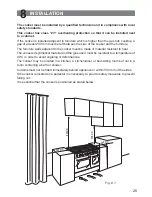
Page 25: ...the furniture The furniture walls adjacent to the cooker must be made of material resistant to heat The veneered synthetical material and the glue used must be resistant to a temperature of 90 C in or...

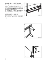
Page 26: ...e rear of the cooker on a piece of the polystyrene packaging exposing the base for the fitting of the feet Fit the 4 legs by screwing them tight into the support base as shown in figure 8 3 LEVELLING...

Page 27: ...t this manoeuvre to prevent damage to the adjustable feet fig 8 5 WARNING Be carefull Do not lift the cooker by the door handle s when raising to the upright position fig 8 6 WARNING When moving cooke...

Page 28: ...STABILITY BRACKET OR STABILITY CHAIN Due to varying site and installation requirements stability devices are not supplied with this appliance It is therefore the responsibility of the suitably qualifi...

Page 29: ...side air in which case no permanent ventilation is required For rooms with a volume greater than 10 m3 no permanent ventilation is required NB Regardless of room size all rooms containing the applianc...

Page 30: ...above quoted regulation GAS INSTALLATION REQUIREMENTS Important The walls adjacent to the cooker must be of heat resistant material Before installation make sure that the local distribution condition...

Page 31: ...hnical knowledge of electricity should install the appliance He should observe the Regulations and Codes of Practice governing such installation of gas appliances Note It is recommended that the gas c...

Page 32: ...ig 9 2 The unused end inlet pipe must be closed with the plug interposing the gasket After connecting to the mains check that the coupling are correctly sealed using soapy solution but never a flame G...

Page 33: ...33 700 mm Rear wall Suggested area for gas mains connection 200 mm IMPORTANT PRESCRIPTIONS FOR GAS CONNECTION Fig 9 3...

Page 34: ...IR VENT NECESSARY FOR GAS COMBUSTION 2 m3 h x kW BURNERS Air necessary for combustion m3 h Auxiliary A 2 00 Semi rapid SR 3 50 Rapid R 6 00 Triple ring TR 7 00 LUBRICATION OF THE GAS TAPS In case of d...

Page 35: ...F Fig 9 6 REPLACEMENT OF THE INJECTORS Select the injectors to be replaced accor ding to the Table for the choice of the injectors If the injectors are not supplied they can be obtained from the Servi...

Page 36: ...ppliance must be di sconnected from the network WARNING ELECTRICITY CAN BE EXTREMELY DANGEROUS THIS APPLIANCE MUST BE EARTHED ELECTRICAL FEEDER CABLE CONNECTION The operations must be executed by a qu...

Page 37: ...rical supply The appliance should be connected to a DOUBLE POLE SWITCHED FUSED SPUR OUTLET similar to that shown in Fig 10 3 We recommend that the appliance is connected by a suitably qualified person...

Page 38: ...38...

Page 39: ...39...

Page 40: ...due to printing or transcription errors in the present booklet The manufacturer reserves the right to make all modifications to its products deemed necessary for manufacturer commercial reasons at an...

Reviews: