28
F I X T U R E I N S T A L L A T I O N
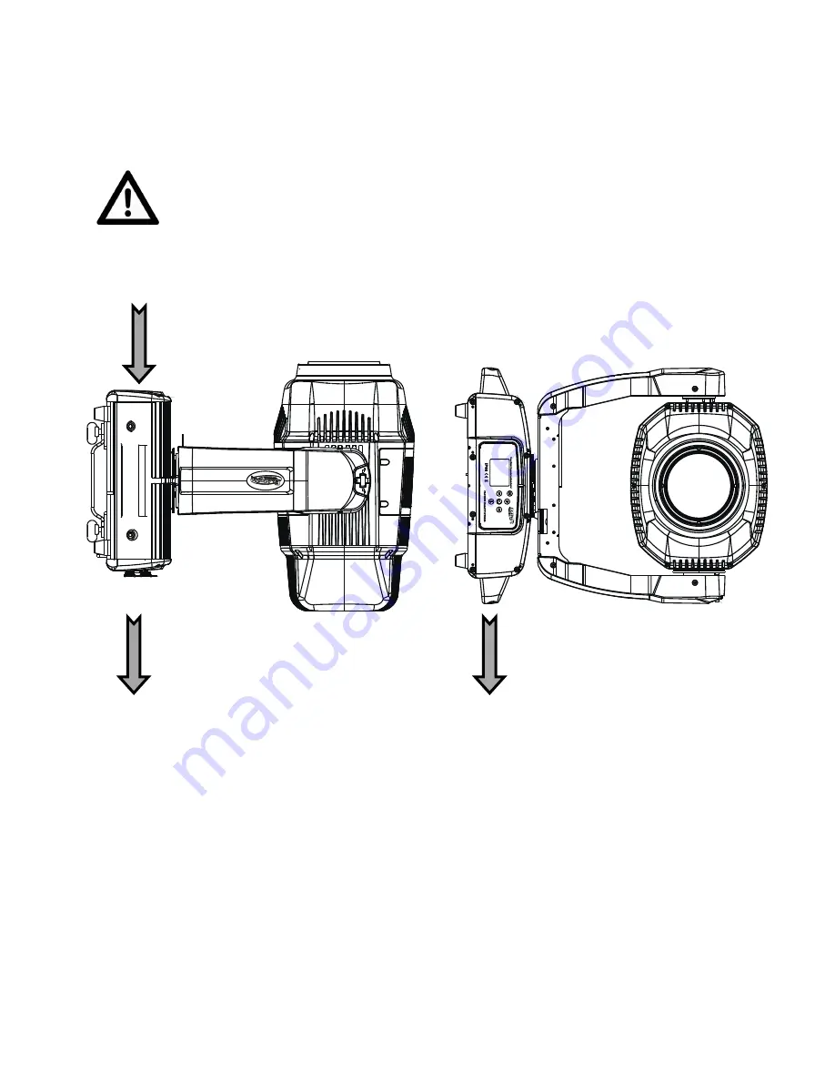
POWER AND DATA CABLES
TO MAINTAIN THE IP65 RATING INTEGRITY OF THE FIXTURE, ALL CABLES
MUST BE RUN TOWARDS THE GROUND TO PREVENT WATER
ACCUMULATION AROUND THE CONNECTIONS. (see illustration below)
CONTROL PANEL LCD DISPLAY
CABLES
CABLES


