background image

27

R E C O R D   C O N T R O L L E R

The fixture features an integrated DMX recorder that can be used to transmit the pro-

grammed scenes from your DMX controller to the moving head. Adjust the desired scene num-

bers via the encoder (from – to). When you call up the scenes with your controller, they will 

automatically be transmitted to the moving head.

WORKING WITH BUILT-IN PROGRAMS 

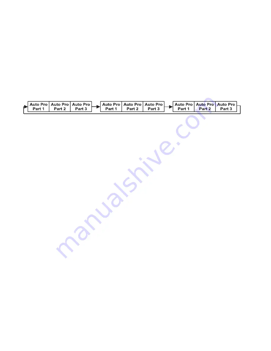
A Primary unit can send up to 3 different data groups to the Secondary units. In other words, 

a Primary unit can operate up to 3 different Secondary units, with each Secondary unit oper-

ating a different set of programs. The Primary unit sends the 3 program parts in a continuous 

loop.


The Secondary unit receives data from the Primary unit according to the group that the Sec-

ondary unit was assigned to. For example, suppose we have a unit that has been assigned as a 

“Secondary 1” unit. Upon receiving the 3-part Auto Program from the Primary unit, the Sec-

ondary 1 unit will implement Part 1 of the Auto Program, while ignoring Part 2 and Part 3.

To start running an Auto Program, follow the directions below:

1.  Set the Secondary unit(s) to the desired Secondary group.

 In the main menu of any 

unit that you want to set as a Secondary, navigate to Function > Secondary Mode. Select 

“Secondary 1”, “Secondary 2”, or “Secondary 3” to designate the desired Secondary group. 

Press ENTER to confirm, and press MODE/ESC to return to the main menu,

2.  Set the Primary unit.

 In the Main Menu of the unit you want to set as the Primary, navi-

gate to Function > Auto Program. Select “Primary” and press ENTER to confirm. Then press 

MODE/ESC to return to the main menu.

3.  Program selection for each part of the Auto Program.

 In the main menu of the Primary 

unit, navigate to Edit Program > Select Programs. Select “Auto Pro Part 1”, then select 

which program (1 - 10) to set as Part 1. Press ENTER to confirm. Repeat the process for 

“Auto Pro Part 2” and “Auto Pro Part 3”.

4.  Program selection for edit program.

 In the main menu of the Primary unit, navigate to 

Edit Program > Edit Program, then press ENTER. Select the desired program to edit spe-

cific scenes into a specific program, then press ENTER to confirm.

5.  Automatic Scene Recording.

 In the main menu of the Primary unit, navigate to Edit Pro-

gram > Edit Scenes, then press ENTER. Select the desired scene numbers, noting that a 

maximum of 250 scenes can be programmed. Press ENTER to confirm.

See the following page for an example.

Summary of Contents for PROTEUS RAYZOR 1960

Page 1: ...User Manual PROTEUS RAYZOR 1960...

Page 2: ...ct economic loss associated with the use or reliance of any information contained within this document and or as a result of the improper unsafe insufficient and negligent assembly installation riggin...

Page 3: ...22 Control Panel 23 System Menu 24 Record Controller 27 Fan Control and Low Noise Operation 29 Lighting Console Patching Guidelines 30 DMX Traits 35 FX Generator Guidelines 46 RGBW Pixel FX Table 47 S...

Page 4: ...environments and has been designed with an enclosure that effectively protects the ingress entry of external foreign objects such as dust and water The International Protection IP rating system is co...

Page 5: ...first purchased Please refer to the Dimensional Drawings section of this manual for detailed information about the foam in lay Additionally it is CRITICALLY IMPORTANT to orient the head of the fixture...

Page 6: ...ed freight pre paid and insured to ELATION in Los Angeles CA or an ELATION Authorized Service Center The RMA number must be clearly written on the outside of the return box and a brief description of...

Page 7: ...from the misuse of this fixture due to the disregard of the information printed in this manual Only qualified and or certified personnel should perform installation of this fixture and only the origi...

Page 8: ...on slots All fan and air inlets must remain clean and never blocked Leave approx 6 15cm between the fixture and other devices or a wall in order to allow for proper cooling Always disconnect the fixtu...

Page 9: ...during normal operation resulting in damage or injury as larger parts could fall Check for any deformations on the housing color lenses rigging hardware and rigging points ceiling suspension trussing...

Page 10: ...ap for the battery compartment as shown below to the left 2 Remove old battery and replace Make sure the battery is oriented with the negative terminal towards the inside and the positive terminal tow...

Page 11: ...Lens Tilt Lock Display Screen Mode Esc Button Left Button Down Button Enter Button Right Button Up Button Pan Lock Carrying Handle Air Valve Power Input RJ45 Input RJ45 Output DMX Input DMX Output Ba...

Page 12: ...these qualifications do not attempt the installa tion yourself Improper installation can result in bodily injury Fixture ambient operating temperature range is 4 to 113 F 20 to 45 C Do not operate th...

Page 13: ...ure see lower illustation Secure the Omega Brackets to the fix ture by turning each quick lock fastener turn clockwise Always check to make sure that each fastener is completely locked SAFETY CABLE AL...

Page 14: ...nd securely Thread each bolt into the match ing 12M holes on the underside of the fixture as shown in the illustration below Both bolt must be threaded to a depth of at least 18mm 0 7in into the fixtu...

Page 15: ...of all installation mate rial and the fixture among other skills If you lack these qualifications do not attempt the installation yourself Improper installation can result in bodily injury The fixture...

Page 16: ...TURE ALL CABLES MUST BE RUN TOWARDS THE GROUND IN ORDER TO PREVENT WATER ACCUMULATION AROUND THE CONNECTIONS RJ45 DATA CABLES THE INCLUDED RJ45 DATA CABLE IS FOR FIXTURE TO FIXTURE INTERCONNECTIONS ON...

Page 17: ...ers iris shutters motors belts wiring discharge lamps and LEDs This issue is not specific only to Elation lighting fixtures but rather it is a common issue with lighting fixtures from all manufacturer...

Page 18: ...ENU SUB MENU OPTIONS Personality Status Settings No DMX Status Sun Protection default Close Hold Auto Program The sun protection position is activated under the following conditions Power on without D...

Page 19: ...ote DMX control Press and hold Hibernate Fixture for 3s Hibernation mode is deactivated under the following conditions DMX signal is connected Remote DMX control Hold Hibernate Off for 3s The fixture...

Page 20: ...9 lb in 10 1 kgf cm 2 Arm Cover 8 7 0 9 lb in 10 1 kgf cm 3 Lower Head Cover 8 7 0 9 lb in 10 1 kgf cm 4 Upper Arm Cover 8 7 0 9 lb in 10 1 kgf cm 5 Handle 20 0 2 0 lb in 23 2 3 kgf cm 6 Display Board...

Page 21: ...DETAILS CAUTION THE USE OF PROTECTIVE GLOVES AND SAFETY GOGGLES IS STRONGLY RECOMMENDED WHILE PERFORMING THE IP PRESSURE TEST AVOID PLACING YOUR FACE EYES HANDS ETC IN CLOSE PROXIMITY TO THE FIXTURE...

Page 22: ...well as allowing the fixture to respond known as a GET command The controller can then use its SET command to modify settings that would typically have to be changed or viewed directly via the unit s...

Page 23: ...OWN buttons to adjust the setting options for that field Pressing the ENTER button once more will confirm your setting You may exit the main menu at any time without making any adjustments by pressing...

Page 24: ...me Total Run Time xxxx hours Fixture running time Last Run Time xxxx hours Run time since last reset Clear Last Run Password 038 On Off Clear last run time Temperature Info LED Temperature xxx C F Hea...

Page 25: ...ff Normal orientation On Inverted orientation Auto Automatically switch orienta tion to keep display upright Key Lock On Off Temperature C F Celsius Fahren Initial Status Pan xxx Initial effect positi...

Page 26: ...ODE SET User Mode Standard Mode Pixels Extended Mode EDIT PROGRAM Select Program Auto Pro Part 1 Program 1 10 Default Program 1 Auto Pro Part 2 Program 1 10 Default Program 1 Auto Pro Part 3 Program 1...

Page 27: ...ry unit s to the desired Secondary group In the main menu of any unit that you want to set as a Secondary navigate to Function Secondary Mode Select Secondary 1 Secondary 2 or Secondary 3 to designate...

Page 28: ...ludes scenes 10 11 12 13 Program 4 includes scenes 8 9 10 Program 6 includes scenes 12 13 14 15 Auto Pro Part 1 is Program 2 Auto Pro Part 2 is Program 3 Auto Pro Part 3 is Program 6 The 3 Secondary g...

Page 29: ...Fan speeds are reduced throughout the fixture for a lower noise profile The fixture output is also reduced to approximately 80 This mode should be sufficient for most uses where lower noise is requir...

Page 30: ...ty of options for controlling each fixture efficiently The main fixture contains 19 x 60W RGBW pixel cells while the SparkLED fixture contains 76 x 2W white LEDs For ease of use the DMX layout is arra...

Page 31: ...19 RGBW Pixel Rings Ring 1 1 2 3 7 12 16 19 18 17 13 8 4 Ring 2 5 6 11 15 14 9 Ring 3 10 Spark LED Rows Row 1 1 3 Row 2 4 9 Row 3 10 16 Row 4 17 24 Row 5 25 33 Row 6 34 43 Row 7 44 52 Row 8 53 60 Row...

Page 32: ...programming of the fixture Use the PROTEUS RAYZOR 1960 in Extended mode and patch appropriate parts of the RGBW Pixels and SparkLED fixtures on your control system to access all 176 channels On the l...

Page 33: ...33 L I G H T I N G C O N S O L E PAT C H I N G G U I D E L I N E S ONYX screen shots below illustrate Main and Sub Fixture ID patch for a single PROTEUS RAYZOR 1960 fixture...

Page 34: ...election of a single PROTEUS RAYZOR 1960 fixture Group Name Group Content All RGBW Pixels Main 1 All RGBW Pixels 1 1 1 2 1 20 All Spark LEDs Main 1 20 All Spark LEDs 101 1 101 2 101 76 ONYX screen sho...

Page 35: ...o slow 127 129 No Rotation fixture stops at current position 130 253 Counter Clockwise Rotation slow to fast 254 255 No Rotation fixture stops at current position 6 6 6 Tilt Rotate Fade 0 000 002 Disa...

Page 36: ...Medium Purple 095 099 Mid Rose 100 104 Mauve 105 109 Nice Magenta 110 114 Warm Magenta 115 119 Light Red 120 124 Straw 125 129 Dark CTB 130 134 Light Green 135 139 Purple 140 144 Lighter Purple 145 1...

Page 37: ...fast 224 255 Shutter Open 10 10 10 000 255 Dimmer 0 to 100 Fade 0 11 11 11 000 255 Dimmer Fine Fade 0 12 12 12 Dim Modes Snap 0 000 020 Standard 021 040 Stage 041 060 TV 061 080 Architectural 081 100...

Page 38: ...ion 14 16 16 Control Snap 0 000 010 Idle 011 012 Pan Tilt Shortest Path 013 014 Pan Tilt Continue Path default 015 016 Pan Range 540 default 017 018 Pan Range 360 019 020 Tilt Range 270 default 021 02...

Page 39: ...070 118 1080 119 1090 120 1100 121 1110 122 1120 123 1130 124 1140 125 1150 126 1160 127 1170 128 1180 129 1190 130 1200 131 1210 132 1220 133 1230 134 1240 135 1250 136 1260 137 1270 138 1280 139 129...

Page 40: ...199 200 Sun Protection Off 201 210 Dimmer Curve Linear default 211 220 Dimmer Curve Square 221 230 Dimmer Curve Inverse Square 231 240 Dimmer Curve S Curve 241 242 Zoom Speed Slow 243 244 Zoom Speed...

Page 41: ...0 to 100 Fade 255 29 29 000 255 White 2 0 to 100 Fade 255 30 30 000 255 Red 3 0 to 100 Fade 255 31 31 000 255 Green 3 0 to 100 Fade 255 32 32 000 255 Blue 3 0 to 100 Fade 255 33 33 000 255 White 3 0...

Page 42: ...00 255 Green 12 0 to 100 Fade 255 68 68 000 255 Blue 12 0 to 100 Fade 255 69 69 000 255 White 12 0 to 100 Fade 255 70 70 000 255 Red 13 0 to 100 Fade 255 71 71 000 255 Green 13 0 to 100 Fade 255 72 72...

Page 43: ...LED Dimmer 2 0 to 100 Fade 255 103 000 255 Spark LED Dimmer 3 0 to 100 Fade 255 104 000 255 Spark LED Dimmer 4 0 to 100 Fade 255 105 000 255 Spark LED Dimmer 5 0 to 100 Fade 255 106 000 255 Spark LED...

Page 44: ...100 Fade 255 141 000 255 Spark LED Dimmer 41 0 to 100 Fade 255 142 000 255 Spark LED Dimmer 42 0 to 100 Fade 255 143 000 255 Spark LED Dimmer 43 0 to 100 Fade 255 144 000 255 Spark LED Dimmer 44 0 to...

Page 45: ...mer 67 0 to 100 Fade 255 168 000 255 Spark LED Dimmer 68 0 to 100 Fade 255 169 000 255 Spark LED Dimmer 69 0 to 100 Fade 255 170 000 255 Spark LED Dimmer 70 0 to 100 Fade 255 171 000 255 Spark LED Dim...

Page 46: ...126 Reverse fast to slow 127 128 Stop 129 255 Forward slow to fast FX for RGBW and Spark LED contain a selection channel to recall the desired pattern The pattern direction and speed is then adjusted...

Page 47: ...and reverses 15 015 Rows Reverse Stop Forward Row1 2 3 4 5 16 016 Rows Bounce Reverse Stop Forward Rows forward once and reverses 17 017 Column Reverse Stop Forward One column per step 18 018 Column...

Page 48: ...ring 3 one pixel at a time then erases ring 1 then ring 2 then ring 3 one pixel at a time 44 044 Ring Build Erase 2 Reverse Stop Forward Builds ring 1 then ring 2 then ring 3 one pixel at a time then...

Page 49: ...sabled 1 2 4 5 8 9 13 14 17 18 124 124 Disabled 2 3 6 7 11 12 15 16 18 19 125 130 125 130 Not in use Color 131 131 RGBW Cells Reverse Stop Forward Every pixel randomly selects R G B or W on each step...

Page 50: ...l randomly picks red or white on each step 149 149 Green White Cells Reverse Stop Forward Every cell randomly picks green or white on each step 150 150 Blue White Cells Reverse Stop Forward Every cell...

Page 51: ...t full flashes once over the cur rently mixed color on all cells 162 162 Color Wheel Flash Reverse Stop Forward Selected color wheel color at full flashes once over the currently mixed color on all ce...

Page 52: ...ls Reverse Stop Forward Randomly lights 4 pixels per step 16 016 5 Pixels Reverse Stop Forward Randomly lights 5 pixels per step 17 017 10 Pixels Reverse Stop Forward Randomly lights 10 pixels per ste...

Page 53: ...right row 6 right to left row 7 left to right 32 100 032 100 No function Full Lens Patterns 101 101 Single Reverse Stop Forward 1 2 3 19 102 102 Single Bounce Reverse Stop Forward 1 2 3 19 18 17 16 1...

Page 54: ...p then 3 random pixels then 4 random pixels 132 132 Ring Build Reverse Stop Forward Adds one pixel per step in Ring 1 then Ring 2 then Ring 3 133 133 Ring Build Erase Reverse Stop Forward Adds one pix...

Page 55: ...park LEDs in lens 1 5 10 15 19 220 220 Backslash Disabled All Spark LEDs in lens 3 6 10 14 17 221 221 Arrow Left Disabled All Spark LEDs in lens 1 4 8 13 17 9 10 11 12 222 222 Arrow Right Disabled All...

Page 56: ...56 WAV E F O R M S Sinewave Step Sawtooth Ramp Up Ramp Down...

Page 57: ...20 1860 1940 Architectural 1380 1730 2040 2120 Theatre 1580 1940 2230 2280 Stage 2 0 1100 0 1660 Rise Time ms Down Time ms Rise Time ms Down Time ms Rise Time Down Time Dimming Curve Ramp Effect 0 sec...

Page 58: ...040 3500 041 3550 042 3600 043 3650 044 3700 045 3750 046 3800 047 3850 048 3900 049 3950 050 4000 051 4050 052 4100 053 COLOR TEMPERATURE K DMX VALUE 4150 054 4200 055 4250 056 4300 057 4350 058 440...

Page 59: ...500 121 7550 122 7600 123 7650 124 7700 125 7750 126 7800 127 7850 128 7900 129 7950 130 8000 131 8050 132 8100 133 8150 134 8200 135 8250 136 8300 137 8350 138 8400 139 COLOR TEMPERATURE K DMX VALUE...

Page 60: ...e XLR connector is the ouput The first unit in the chain pri mary will use the female XLR connector only while the last unit in the chain will use the male XLR connector only 2 On the primary unit use...

Page 61: ...make the following determinations 3 or More Errors The fixture cannot function properly with three or more errors and therefore the fixture will place itself in stand by mode until subsequent repairs...

Page 62: ...ACT ELATION SERVICE FOR FURTHER INFORMATION An Elation E Loader III can be used to update the fixture to the latest software Please visit the E Loader III product page at the Elation web site and down...

Page 63: ...85in 478 72mm 15 00in 381 09mm 15 00in 381 09mm 4 37in 111 00mm 18 41in 467 68mm 19 78in 502 50m 12 73in 323 39mm 4 94in 125 50mm 13 03in 331 00mm 9 49in 241 00mm 5 31in 134 90mm 22 80in 579 04mm 14...

Page 64: ...N G S FOAM IN LAY 21 1in 535 0mm 19 1in 484 3mm 18 5in 470 0mm 14 2in 360 2mm 9 1in 230 0mm 14 6in 370 8mm 16 3in 415 0mm 17 1in 435 0mm 19 9in 506 6mm 20 9in 530 0mm 0 8in 20 0mm 1 2in 31 0mm 4 9in 1...

Page 65: ...Color Presets and Macros Electronic Strobe and Variable Dimming Curves 16 bit Dimming Pan Angle 360 continuous rotation 540 Tilt Angle 360 continuous rotation 270 CONTROL CONNECTIONS 3 DMX Channel Mod...

Page 66: ...d and used in accordance with the included instructions may cause harmful interference to radio communications However there is no guarantee that interference will not occur in a particular installati...

Page 67: ...67...

Page 68: ......

Reviews: