background image

- Clear fixture time 

With this function you can clear the running time of the device.


1.  Select 

“CLMT”

 by pressing 

[UP]

 or 

[DOWN]

 button. 

2.  Press

 [ENTER]

, the display shows 

“ON”

 or 

“OFF”

3.  Press 

[UP]

 to select 

“ON”

 if you wish to enable this function or press 

[DOWN]

 button to

 “OFF”

 if you don’t.       

4.  Press 

[ENTER]

 to confirm or Press 

[MODE/ESC]

 to return to the main menu. 


- Main menu 3 


1.  Press 

[MODE/ESC]

 to enter the main menu (display flashing). 

2.  Press 

[UP]

 or 

[DOWN]

 button to select 

“EDIT”


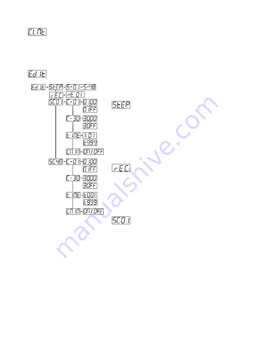
- Define the number of steps in Run 

With this function you can define the number of steps in the Program 
Run. 
1. Select 

“STEP”

 by pressing 

[UP]

 or 

[DOWN]

 button. 

2. Press

 [ENTER]

, the display shows 

“S-XX”

, “X” stands   

for the total amount of steps you want to save, so you can   

call up to 48 scenes in 

“RUN”

. For example if the “XX” is 05, it 

means that 

“RUN”

 will run the first 5 scenes you saved in 

“EDIT”

3. Press 

[ENTER]

 to confirm or Press 

[MODE/ESC]

 to return to 

the main menu. 
 

 -Auto Save 

With this function you can automatic save the number of steps in the 
Program Run. 
1. Select 

“REC”

 by pressing 

[UP]

 or 

[DOWN]

 button. 

2. Press

 [ENTER]

, the display shows 

“RE.XX”

,

 “XX”

stangs for 

the number from 1 to 400.           

3. Press 

[ENTER]

 to confirm or Press 

[MODE/ESC]

 to return to 

the main menu. 


- Editing the channels of the individual scenes 

With this function you can edit the program to be called up in Run. 
 

a) Editing via the Control Board 

1. Select 

“SC01”

 by pressing 

[UP]

 or 

[DOWN]

 button. 

2. Press 

[ENTER]

, the display shows 

“SCXX”

, “X” stands for the scene no. to be edited. 

3.  Change the scene no. by pressing 

[UP]

 or 

[DOWN]

 button. 

4. Press 

[ENTER]

, the display shows

 “C-X”

, “X” stands for the channel no. Such as 

“C-01”

, it means you are     

editing channel 1 of the selected scene. 
5.  Select the channel no. you would like to edit by pressing 

[UP]

 or 

[DOWN]

 button.   

6. Press 

[ENTER]

 to enter editing for the selected channel , the fixture reacts to your settings. The display shows   

the DMX value of the edited channel. Such as “ 11XX”, it stands for in the channel 11 of the editing scene, the 
DMX value is XX , XX is a hexadecimal number value “01-FF”. 
7.  Adjust the desired DMX value by pressing 

[UP]

 or 

[DOWN]

 button. 

8. Press 

[ENTER]

 in order to edit other channels of this scene. 

9.  Repeat steps 5-9 until you finish setting all the DMX values for all channels of this scene. 
10.  Once all the channels completed, the display will flash   

“TIME”


11. Press 

[ENTER] 

to edit the time needed, the display shows 

“TXXX”

 ,

 “XXX”

stands for the time needed to run 

the current scene, value “001-999”. E.g., “002” means you need 0.4ms(002*0.2ms) to run the current scene. 

                                                                                                    - 

12

 -                               XM080-V1.0 NR     


Summary of Contents for DESIGN PROMO 360

Page 1: ...DESIGN PROMO 360 USER MANUAL...

Page 2: ...there be any consult your dealer and don t install this device Features 16 bit resolution Movement 540 630 optional For smooth and precise resolution Can rotate continuously While Channel 4 on DMX va...

Page 3: ...by manual modifications to the device are not subject to warranty Keep away from children and non professionals GENERAL GUIDELINES This device is a lighting effect for professional use on stages in di...

Page 4: ...ate safety cable Never stand directly below the device when mounting removing or servicing the fixture The operator has to make sure the safety relating and machine technical installations are approve...

Page 5: ...stall the second Omega holder Pull the safety rope through the holes on the bottom of the base and over the trussing system or a safe fixation spot Insert the end in the carabine and tighten the safet...

Page 6: ...the digital control information sent out from the DMX controller The allocation of this starting address is achieved by setting the correct number on the display located on the base of the device You...

Page 7: ...address This situation can occur if the 3 PIN XLR plug cable with DMX signal from controller is not connected with the input of the device the controller is switched off or defective if the cable or...

Page 8: ...atic Run as Master ALON SO A Sound controlled Run in Stand Alone RUN SOUN MAST SO M Sound controlled Run as Master VALU D XX D 00 DXXX Display the DMX 512 value of each channel RDIS ON OFF Reverse dis...

Page 9: ...r pressing MODE ESC to return to main menu Slave setting With this function you can define the device as slave 1 Select SLAV by pressing UP or DOWN button 2 Press ENTER the display shows ON or OFF 3 P...

Page 10: ...desired channel If you select D 14 the display will only show the DMX value of the 14th channel 4 Press ENTER to confirm or Press MODE ESC to return to the main menu Reverse display With this functio...

Page 11: ...the main menu Pan degree select With this function you can select pan angle 6300 or 5400 1 Select DEGR by pressing UP or DOWN button 2 Press ENTER the display shows 630 or 540 3 Press UP or DOWN butt...

Page 12: ...of the device All settings will be set back to the default values shaded Any edited scenes will be lost 1 Select LODA by pressing UP or DOWN button 2 Press ENTER the display shows ON or OFF 3 Press UP...

Page 13: ...or Press MODE ESC to return to the main menu Editing the channels of the individual scenes With this function you can edit the program to be called up in Run a Editing via the Control Board 1 Select S...

Page 14: ...DOWN button 5 Press ENTER the display shows OFF 6 Press UP or DOWN button the display shows ON 7 Press ENTER the display shows SC02 You successfully downloaded the first scene 8 Adjust the Step time...

Page 15: ...be correct by a technician The errors in question will remain flashing in the display as a reminder of internal errors 01 Er pan movement wheel error The pan movement wheel is not located in the defa...

Page 16: ...C 60Hz 230VAC 60Hz 240VAC 60Hz Power consumption max 45W Motors 1 micro motors PCB model MH 250 PT 05D PCB fuse F1 4L F2 5L 2PCS Packing dimensions 45x31x49cm Net weight 10 5 KGS Gross weight 14KGS Re...

Reviews: