background image


II.


ASSEMBLY 
 

1.


Unscrew the mounting plate on the left side of the Zippy power supply unit. Keep the screws for later use 

2.


Place de PSU inside the case 

3.


Fix the PSU to the right side plate using the screws removed in step 1 and to the extra plate so it gets fixed to 
the base of the case using the additional screws available 


4.


Match the faceplate on the back of the case to each port on the back of the motherboard 

5.


Remove the protective plastic sticker off the LCD screen 

6.


Screw the LCD screen to the case 

7.


Screw the motherboard to the bottom of the case 

8.


Insert the memory module in the motherboard’s memory slot 

9.


Connect the 24-pin ATX power connector coming from the PSU to the motherboard’s power connector (2 x 12) 

10.


Screw the fan to the left side of the case and connect its power cord to the PSU 

11.


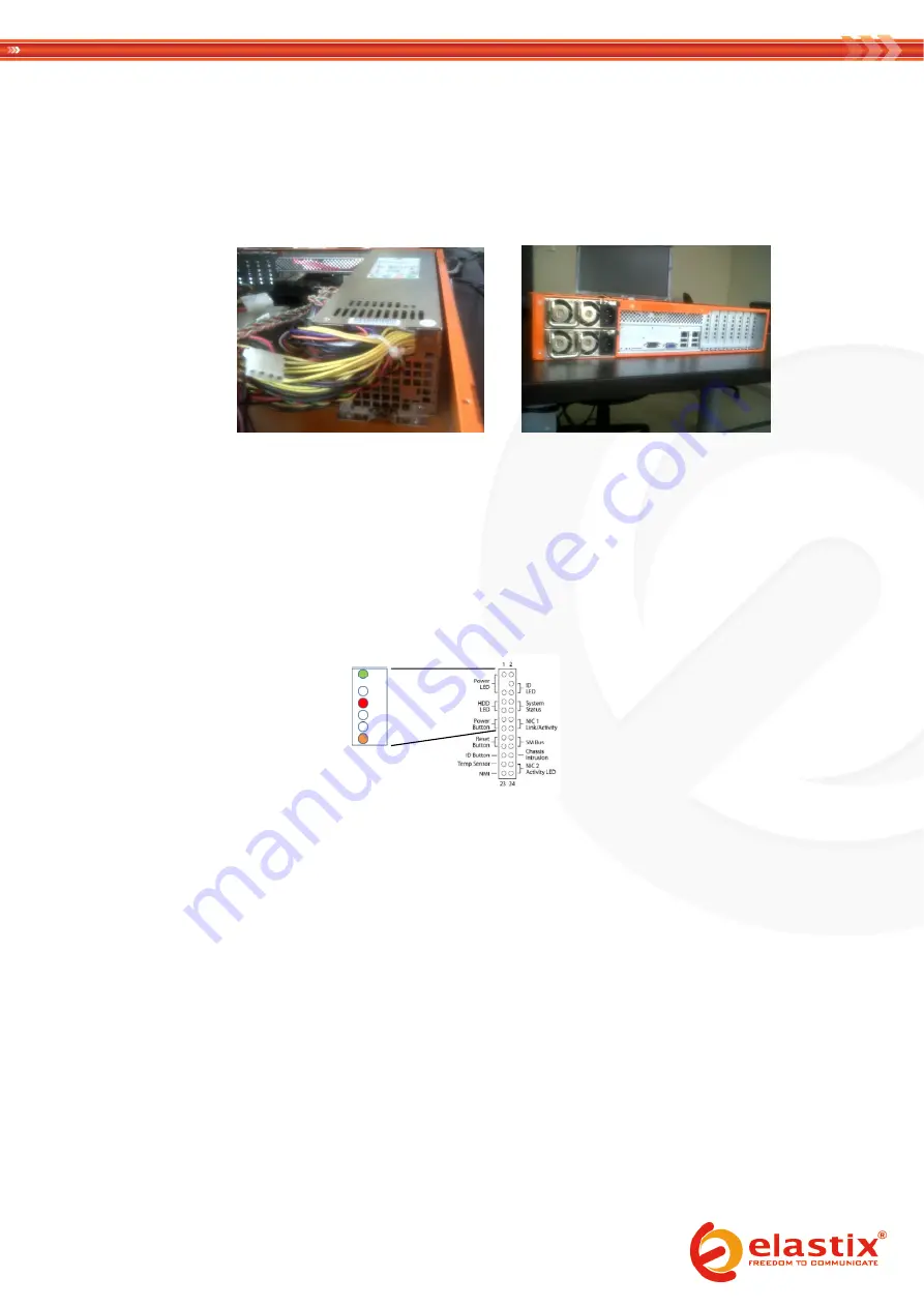
Connect the POWER SWITCH cable (orange-white) to the motherboard 

12.


Connect the HDD LED and Power cables (green-white and red-white , respectively) to the motherboard 


13.


Screw the SATA disk to the bottom of the case 

14.


Connect the data cable of the SATA disk to the motherboard 

15.


Connect the power cable of the SATA disk to the PSU 

16.


Connect the provided USB cable (WRUSBY11) from the LCD panel (CFA635-TFE-KU1) to an internal USB port of 
the motherboard 

17.


Secure cables conveniently using nylon cable ties 
 

NOTE: the assembly process will be completed in the VII. PACKAGING section of this document, once the installation of 
Elastix has been finished and tested 


III.


PRE-INSTALLATION 
 

1.


Connect the data and power cables of a SATA CD or DVD drive to the motherboard 

(skip this step if installing 

Elastix from an external optical drive instead)


2.


If instead an external optical drive is used for the installation (

not recommended

), connect it to the 

corresponding port on the back of the ELX-5000 

3.


Connect the Power Cord Cable to the PSU connector on the back of the ELX-5000 and then to a nearby outlet 

4.


Press the power button to turn on the appliance 

Green 

(empty) 

White 

Red 

White 
White 

Orange 

Summary of Contents for ELX5000

Page 1: ...Elastix Appliance Assembly Process Guide ELX 5000 PaloSanto Solutions January 2012 ...

Page 2: ...s for Hardware RAID 1 Power Cord Cable N A 110V or 220 V N A Model depends on region it is shipped to 2U customized case EMKO EM 165B N A No Power Supply Unit preinstalled Plate for hard disks mounting in vertical location LCD Crystalfontz CFA635 TFE KU1 LCD USB LCD 20x4 Keypad White Edge LED Backlight LCD USB Cable Crystalfontz WRUSBY11 Cable USB Cable for LCD Panel Redundant Power Supply Unit PS...

Page 3: ...LED and Power cables green white and red white respectively to the motherboard 13 Screw the SATA disk to the bottom of the case 14 Connect the data cable of the SATA disk to the motherboard 15 Connect the power cable of the SATA disk to the PSU 16 Connect the provided USB cable WRUSBY11 from the LCD panel CFA635 TFE KU1 to an internal USB port of the motherboard 17 Secure cables conveniently using...

Page 4: ...sourceforge net projects elastix files Elastix 20PBX 20Appliance 20Software this guide was written using Elastix 2 2 6 Reboot the appliance if necessary until the following screen is displayed IV ELASTIX INSTALLATION 1 Press ENTER to begin the installation 2 Select English as the language for the installation ...

Page 5: ...3 Select us as the type of keyboard 4 Choose Create custom layout ...

Page 6: ...AID swap 4096 MB boot RAID ext3 200 MB RAID ext3 450 GB software RAID 4096 MB software RAID 200 MB software RAID 450 GB Leave the remaining space free for posible High Availability implementations in the future 6 Select to configure the Network Interface ...

Page 7: ...7 Select to activate on boot and to enable IPv4 support 8 Manually assign the IP address 192 168 1 251 24 ...

Page 8: ...9 Enter 192 168 1 1 as the Gateway and Primary DNS addresses 10 Type elx palosanto com as the hostname ...

Page 9: ...11 Select the time zone according to the city where the appliance is going to be used in 12 Type palosanto as the password for root ...

Page 10: ...13 Wait until the package installation finishes 14 After the automatic reboot type palosanto as the password for the MySQL root user ...

Page 11: ...15 Reenter the MySQL root user password just typed 16 Type palosanto as the password for the admin user ...

Page 12: ...t thru patch cord b Configure that NIC on the computer with IP address 192 168 1 1 mask 255 255 255 0 c From a web browser on the computer go to the URL https 192 168 1 251 d Username admin e Password palosanto f Elastix s Dashboard should be displayed 3 Confirm correct access to Elastix s shell via ssh is possible a Open a terminal software on the computer used on the previous test and execute ss...

Page 13: ...ead 5 If instead an external optical drive was used for the installation not recommended disconnect it from the corresponding port on the back of the ELX 5000 6 Place the warranty seals on the telephony cards inside the appliance if applicable 7 Place and screw both covers to the top of the case 8 Place the warranty seals on all three outside edges on the case s top cover the cover with the Elasti...

Reviews: