background image

- 23 -

MAINTENANCE

Operational malfunction

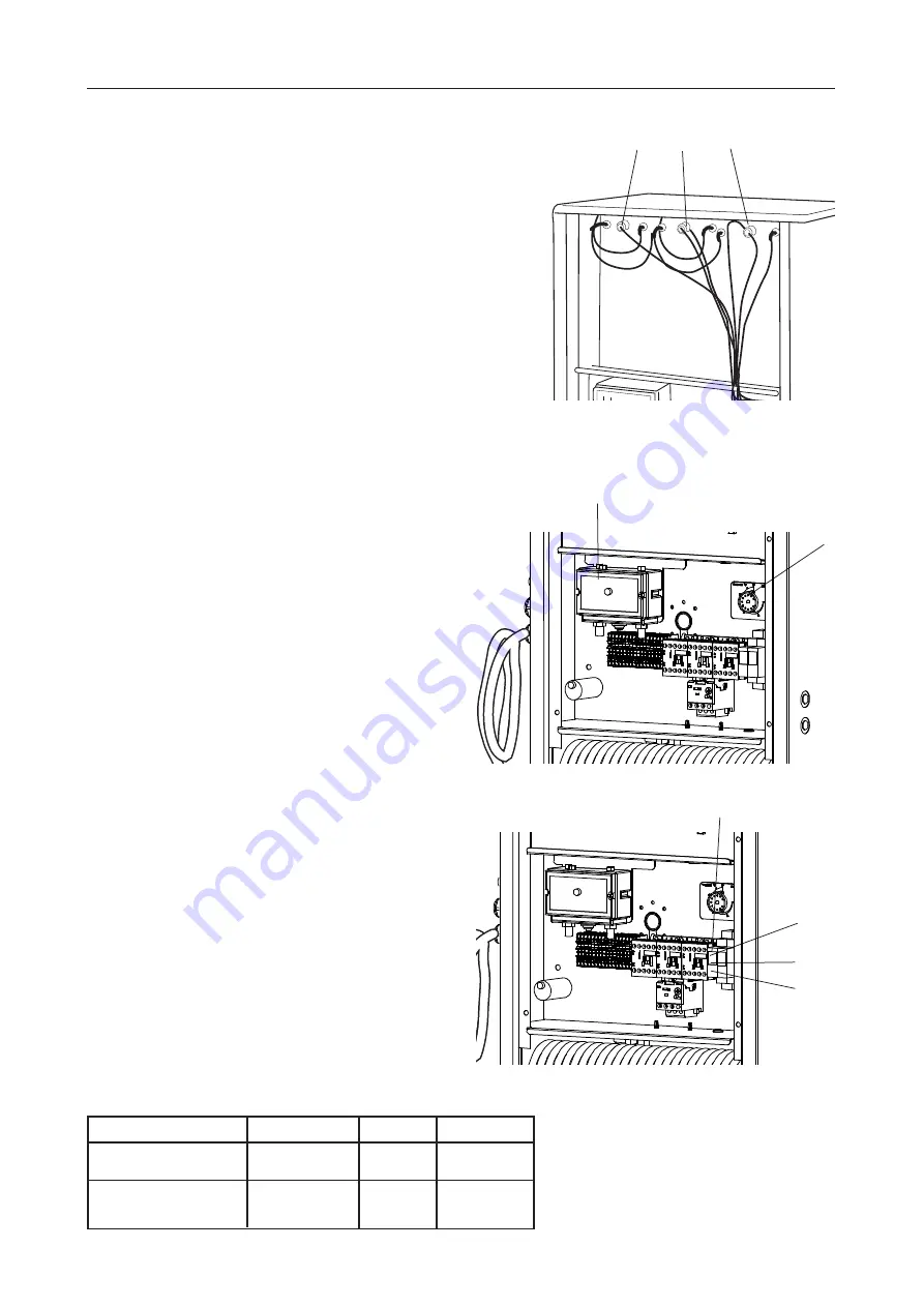
The dehumidifier is equipped with manually resettable 

protector devices for the heating coil and high pressure 

and with a fuse for the electrical control system.

If  the heating coil stops working, it may be due to an 

overheating protector (GT2:1 or GT2:2) being triggered. 

GT2:1 and GT2:2 are located inside the front cover.  

To reset them, follow these steps:

1.  Disconnect the power to the dehumidifier.

2.  Look for the cause of  the protector(s) being 

triggered and fix the fault. The cause may be 

an electrical fault or poor air circulation.

3.  Unscrew the hatch on the dehumidifier.

4.  Reset the protector(s) by depressing sprung  

contacts GT2:1 and GT2:2.

5.  Reattach the hatch, switch on the power and start 

the dehumidifier.

If  the compressor stops and the high pressure light 

(H1) illuminates, the high pressure protector (GP1) 

on the pressure switch has been triggered. Reset the 

protector as follows:

1.  Disconnect the power to the dehumidifier.
2.  Unscrew the hatch on the dehumidifier.

3.  Depress the button GP1.
4.  Reattach the hatch, switch on the power and start 

the dehumidifier.

Time relay (K4)

Timber dehumidifier

When the dehumidifier is used to dry timber, the time 

relay makes it possible to delay start of  operation in 

order to prevent current overload if  multiple units are 

installed. 

Industrial dehumidifier

When the dehumidifier is used as an industrial dryer, 

the time relay has the function of delaying start in 

order to allow a defrost time (approx. 5 minutes) for 

the evaporator when the dehumidifier operates in low 

pressure conditions.

GP1

GT1

GT2:1   GT2:2   GT3

Selector A

Selector 

B

Selector 

C

Setting of selectors on time relay K4

  Application area 

         Selector A          Selector B       Selector C

  Timber dehumidifier          e.g. 1-10 min.        ≥ 0 min.         setting A

   Industrial dehumidifier      e.g. 1-10 min.        ≥ 5 min.         setting A


         or e.g. 6-60 min.


K4

Summary of Contents for A 150 VTI

Page 1: ...Avfuktare A 150VTI Bruksanvisning ...

Page 2: ...derhåll på kylsystemet skall utföras av behörig kylmontör Vid rengöring av förångare och kondensor använd handskar för att undvika skärskador Varning och observera I texten i denna bruksanvisning finns nedanstående rutor på tillämpliga ställen VARNING Dessa rutor varnar för person eller materialskada Varningsrutorna är placerade fram för den procedur som avses OBSERVERA Dessa rutor anger åtgärder ...

Page 3: ... tillsyner skall utföras Den beskriver även vilka åtgärder som skall vidtagas för maximal säkerhet samt hur säkerhetsdetaljerna är utformade och fungerar OBSERVERA Avsnittet som behandlar säkerhet skall läsas och förstås av alla som använder eller reparerar avfuktaren Instruktionsboken omfattar användning och de olika underhållsåtgärder som kan utföras av operatören Mera genomgripande service elle...

Page 4: ...T3 Överhettningsskydd automatisk återställning 4 E GT 2 GT3 H1 Kontrollampa för högtryck röd H2 Kontrollampa för lågtryck röd K1 Kontaktor för fläkt K2 Kontaktor för kompressor K3 Kontaktor för värmebatteri K4 Tidrelä för startfördröjning KD Kondensor Se nästa sida M1 Fläkt Se nästa sida M2 Kompressor Se nästa sida T1 Tidrelä för avfrostning QF1 Motorskydd X Kopplingsplint X2 Anslutningskontakt 5 ...
Page 5: ...ften förångaren AEV där fukten kondenserar och avsätter sig på förångaren Vattnet samlas upp i ett tråg som finns under förångaren och avleds Därefter passerar luften fläkten M1 och kondensorn KD I kondensorn värms luften upp samtidigt som kondensorn kyls Vid behov kan luften därefter värmas i värmebatteriet E innan den lämnar avfuktaren Förångande köldmedium Komponenter AEV Förångare FT Torkfilte...

Page 6: ...et separat motorskydd Motorskyddsfunktionen finns inbyggd i motorns lindningar som stoppar motorn vid förhöjd temperatur Funktionen återställs automatiskt då temperaturen har sjunkit Motorskydd QF1 Skyddar kompressorn mot överlast inställt värde 3 7A Denna bryter hela maskinen om den löser ut Motor skyddet är placerat innanför el luckan Lossa de övre skruvarna på filterluckan Ta bort de fyra skruv...

Page 7: ...ng av slang för kondensvattenavrinning Anslut lämplig slang med fall mot golvbrunn e d Luftcirkulation Avfuktaren placeras lämpligen med baksidan mot en vägg inne i torkutrymmet Fritt utrymme framför skall vara minst 200 mm Fritt utrymme över skall vara minst 500 mm Externa fläktar Om andra fläktar för luftcirkulation finns i torkutrymmet får dessa ej blåsa direkt på avfuktarens inlopp eller utlop...

Page 8: ...en till plint 8 och 9 Använd kabel med area minst 0 75 mm2 3 Ställ avfuktarens interna termostat GT3 på max 4 Elbatteriet reglerar endast då avfuktaren är driftsatt Extern hygrostat RH för automatiskt stopp Extern hygrostat reglerar endast kompressorn via konatktor K 02 Hygrostaten ansluts på följande sätt 1 Tag bort bygeln mellan plint 5 och 6 i anslutningsplinten X 2 Ansluthygrostatentillplint5o...

Page 9: ...jälp av en huv eller kanalböj tillbaka in i containern Containern är försedd med fläktar som gör att luften cirkulerar För ökat resultat kan fläktarna reverseras efter inställd tid så att luftströmmen inne i containern ändrar riktning 1 Container ingår ej i leveransen 2 Axialfläktar ingår ej i leveransen 3 Huv ingår ej i leveransen 4 Avfuktare A 150VTI OBSERVERA Endast avfuktaren som visas i detta...

Page 10: ...vfuktarens interna termostat GT1 på max temperatur Anslut avfuktaren till eluttag och se till att arbetsbrytaren är påslagen Se även bruksanvisningen för den externa styrningen GT1 OBSERVERA Figuren till höger visar endast parallelldrift med automatiskt stopp för 2 avfuktare Parallelldrift av flera avfuktare Då flera avfuktare skall styras parallellt skall de aktuella plintparen kopplas ihop i en ...

Page 11: ...1 tänds har pressostatens högtrycksskydd GP1 löst ut Återställ skyddet enligt följande 1 Koppla bort avfuktarens elanslutning 2 Skruva bort avfuktarens lucka 3 Tryck in knappen GP1 4 Återmontera luckan samt sätt på strömmen och starta avfuktaren Tidrelä K4 Virkestorksavfuktare Vid användnig av avfuktaren som virkestorksavfuktare så är funktionen att ha möjlighet att tidsfördröja uppstart för att m...

Page 12: ...aren Allt underhåll på elsystemet skall utföras av behörig elektriker Allt underhåll på kylsystemet skall utföras av behörig kylmontör Reparation Vid omfattande reparation tag i första hand kontakt med leverantören och i andra hand tillverkaren Tillverkare El Björn AB Tel 0371 588 100 www elbjorn com Varje år Kontrollera varje år nedanstående punkter Punkterna skall kontrolleras av behörig persona...

Page 13: ...s på släpkärra SKROTNING Avfuktaren skall inlämnas till återvinningsstationer i enighet med statliga eller lokala förordningar Avfuktaren upptas i Sverige av regler gällande El kretsen GARANTI Standardavtalet NL09 gäller för El Björn AB s leveranser och produkter Enligt dessa bestämmelser ansvarar El Björn AB för fel som visar sig inom ett år från leveransen För fackmän som registrerar sig enligt ...

Page 14: ... cooling technicians Always wear protective gloves when cleaning the evaporator and condenser to avoid cuts Warnings and notes The text in this instruction contains the following inserts at suitable places WARNING These inserts warn of injury damage to persons or property Warning inserts are placed before the procedure in question NOTE These inserts refer to measures that simplify a certain proced...

Page 15: ...ction of the drying cabinet It also describes which measures shall be taken for maximum safety and how the safety functions are designed and implemented NOTE The section concerning safety shall be read and understood by all who use or repair the dehumidifier The instruction manual contains operation and maintenance measures that can be performed by the operator More detailed service or troubleshoo...

Page 16: ...manual reset 2x GT3 Overheating protection auto reset 16 E GT 2 GT3 H1 High pressure warning light red H1 Low pressure warning light red K1 Contactor for fan K2 Contactor for compressor K3 Contactor for heating coil K4 Time delay relay KD Condenser See following page M1 Fan See following page M2 Compressor See following page T1 Defrost relay QF1 Automatic circuit breaker X Terminal block X2 Connec...
Page 17: ...vaporator AEV where the moisture condenses and is deposited on the evaporator The water is collected in a tray fitted under the evaporator and is drained away The air then passes through the fan M1 and condenser KD In the condenser the air is warmed up and the condenser is simultaneously cooled If necessary the air can be heated up by a heating coil E before leaving the dehumidifier Evaporating re...

Page 18: ... block X Compressor M2 The compressor has no separate automatic circuit breaker The automatic circuit breaker is integrated into the motor windings stopping the motor if it overheats The function resets automatically when the temperature returns to normal Automatic circuit breaker QF1 Protects the compressor against overload set value 3 7 A It shuts down the whole machine if it is tripped The auto...

Page 19: ...able tube which should be routed with a drop towards the floor drain Air circulation The dehumidifier should ideally be placed with its back against a wall inside the drying room There should be at least 200 mm of free space in front of it There should be at least 500 mm of free space above it External fans If other circulation fans are present in the drying room they must not blow directly toward...

Page 20: ... 8 and 9 Use a cable with an area of at least 0 75 mm2 3 Set the dehumidifier s internal thermostat GT3 to the maximum temperature 4 The heating coil will only function when the dehumidifier is in operation External humidistat RH for automatic stopping The external humidistat only controls the compressor via contactor K 02 Connect the humidistat as follows 1 Remove the jumper between blocks 5 and ...

Page 21: ...rom the dehumidifier is conducted back into the container through a duct bend The container is equipped with fans to ensure air circulation For improved results the fans can be reversed after a set time so that the air flow inside the container changes direction 1 Container not included 2 Axial fan not included 3 Hood not included 4 Dehumidifier A 150VTI NOTE Only the dehumidifier shown in this ex...

Page 22: ...internal thermostat GT1 to the maximum temperature Connect the dehumidifier to the electrical supply and make sure the main operating switch is on Also see the instruction manual for the external control system GT1 NOTE The figure to the right only shows parallel operation with automatic stopping for two dehumidifiers Parallel operation of multiple dehumidifiers If multiple dehumidifiers are to be...

Page 23: ...tes the high pressure protector GP1 on the pressure switch has been triggered Reset the protector as follows 1 Disconnect the power to the dehumidifier 2 Unscrew the hatch on the dehumidifier 3 Depress the button GP1 4 Reattach the hatch switch on the power and start the dehumidifier Time relay K4 Timber dehumidifier When the dehumidifier is used to dry timber the time relay makes it possible to d...

Page 24: ...e main operating switch All maintenance on the electrical system must be performed by qualified electricians All maintenance on the cooling system must be performed by qualified cooling technicians Repair If extensive repairs are needed first contact the supplier and then contact the manufacturer if necessary Manufacturer El Björn AB Tel 46 0 371 588 100 www elbjorn com Once a year Check the follo...

Page 25: ... SCRAPPING Take the dehumidifier to a recycling station according to state or local regulations In Sweden the dehumidifier is covered by the El kretsen collection and recycling rules WARRANTY El Björn AB s products and deliveries are regulated by Standard Agreement NL09 Under these provisions El Björn AB is responsible for faults arising within one year after delivery The provisions of NL 09 also ...

Page 26: ... 26 ...

Page 27: ... 27 ...

Page 28: ...KL597005 SE 180228 El Björn AB Box 29 SE 334 21 Anderstorp Sweden Phone 46 0 371 588 100 info elbjorn se www elbjorn com ...

Reviews: