


ARDUINO SHIELD CAPACITIVE TOUCH
User Manual
Introduction:
The
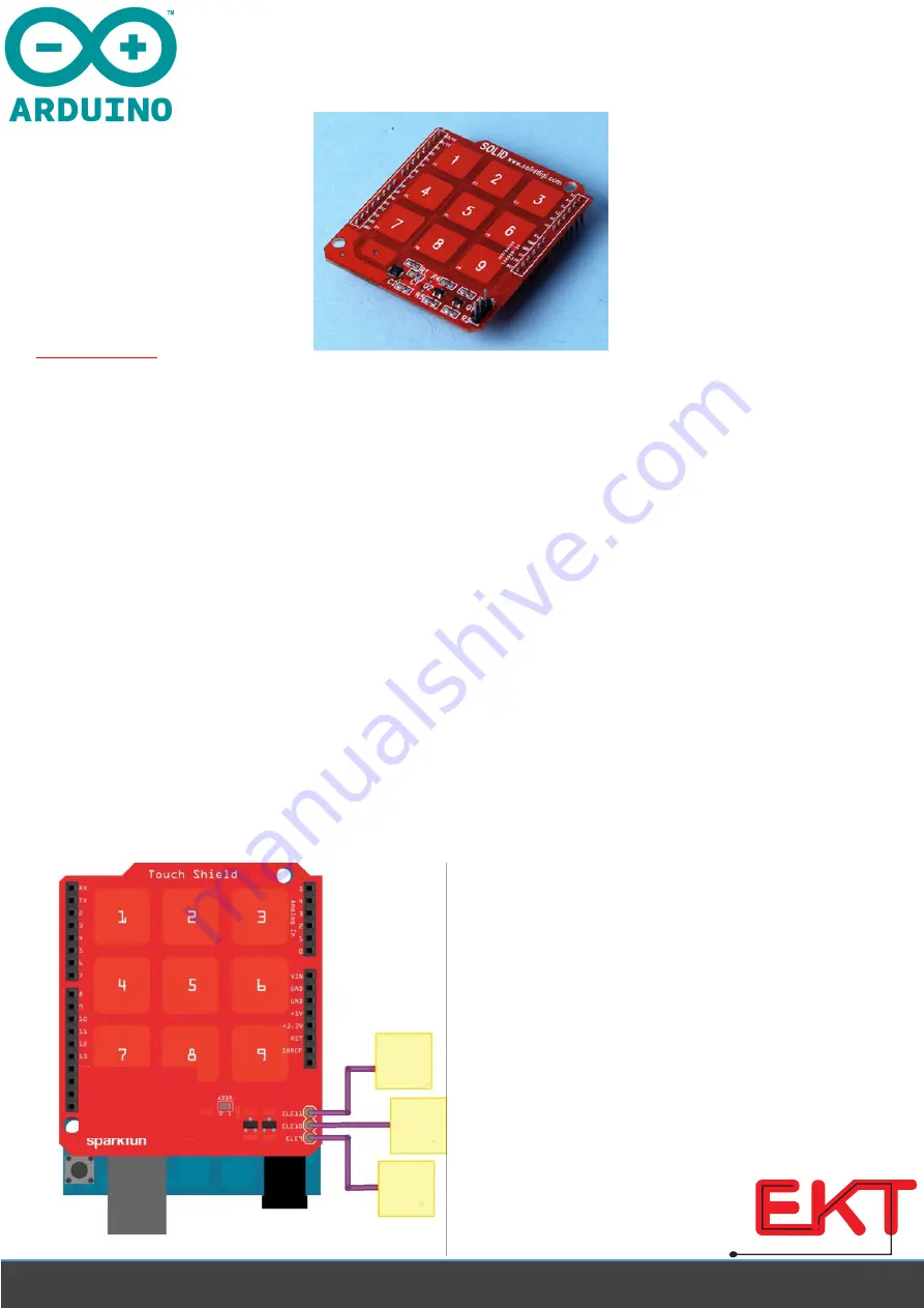
ARDUINO SHIELD CAPACITIVE TOUCH is an Arduino R3 compatible shield that enables capacitive
touch capabilities for your project using the MPR121 IC. The shield itself has 9 touch pads on it
(conveniently numbered 1-9 in a 3x3 grid), and has headers for 3 additional electrode connections.
The shield connects directly to the 3.3V pin on the Arduino. There is no on-board voltage regulation
on the VCC line, so keep that in mind if you intend to use this with a 5V Arduino Pro board. However,
there is an onboard logic level converter to step down 5V levels to the 3.3V for the sensor’s I
2
C lines.
This shield is designed to interface with an Arduino Uno R3. You can use other microcontrollers as
well with the same footprint, such as the Arduino Mega. You will need access to the I
2
C pins, SDA and
SCL. Other than that, you will need access to the 3.3V and GND pins and to digital pin 2. This connects
to the INT pin on the MPR121 sensor.
We generally use stackable headers for attaching shields to Arduino boards, but you can use standard
male headers if you prefer. The
R3 Stackable Header Kit
is the easiest option to use if you are planning
on stackable headers. For detailed instructions on how to assemble your shield, have a look at
our
Shield Tutorial.
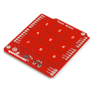
The shield also has 3 pins labeled ELE9, ELE10, and ELE11. These correspond to electrodes 9,10, and
11 on the MPR121 chip. You can solder additional buttons or connections on to these pins at this time
if you want more than the 9 buttons already available on the shield. However, you don’t have to do
this to get the shield to function. It’s up to you!
Check out the Fritzing diagram below to see how your shield should look if you have added buttons on
to your shield on pins ELE9, ELE10, and ELE11.
Note: The yellow squares represent whatever material you’ve chosen to use as your electrode.
Once you’ve got your shield all hooked up, let’s start pulling data from the shield!
w w w . e k t
2
. c o m
Electronics
Katrangi
Trading


