background image


Chapter 1   W

A R R A NT Y


This Pockels cell driver DQ-100-4 is protected by one-year warranty covering labor and 
parts. The warranty enters into validity since the shipment date. Any evidence of improper 
use or unauthorized attempts at repair leads to warranty cancellation. 


In case of service required or any questions on warranty, please notify: 


EKSMA OPTICS 

c/o EKSMA Optics, UAB 

Mokslininku Str. 11 

LT-08412 Vilnius, Lithuania 


Phone: +370 5 272 99 00 

Fax.: +370 5 272 92 99 

E-mail: [email protected]  

Website: www.eksmaoptics.com  


Summary of Contents for DQ-100-4

Page 1: ...DQ 100 4 High Voltage Driver Technical Description 2021 Lithuania ...

Page 2: ...www eksmaoptics com ...

Page 3: ... 2 SERVICE CONTACT INFORMATION 1 CHAPTER 2 SPECIFICATIONS 2 2 1 GENERAL INFORMATION 2 2 1 1 Model 2 2 1 2 Main Components 2 2 2 TECHNICAL SPECIFICATIONS 2 CHAPTER 3 DEVICE LAYOUT 3 CHAPTER 4 SAFETY 5 CHAPTER 5 QUICK START GUIDE 6 CHAPTER 6 IMPORTANT NOTES 8 ...

Page 4: ...ING AND DIMENSIONS OF THE DRIVER 3 FIGURE 2 TOP VIEW OF THE DRIVER 4 FIGURE 3 INPUT CIRCUIT OF DRIVER 7 FIGURE 4 CONTROL TIMING CHARTS 7 LIST OF TABLES TABLE 1 MAIN COMPONENTS 2 TABLE 2 TECHNICAL SPECIFICATIONS 2 TABLE 3 PORTS SEEN IN TOP VIEW OF THE DRIVER 4 ...

Page 5: ... shipment date Any evidence of improper use or unauthorized attempts at repair leads to warranty cancellation In case of service required or any questions on warranty please notify EKSMA OPTICS c o EKSMA Optics UAB Mokslininku Str 11 LT 08412 Vilnius Lithuania Phone 370 5 272 99 00 Fax 370 5 272 92 99 E mail info eksmaoptics com Website www eksmaoptics com ...

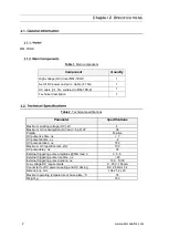
Page 6: ...V 4 Maximum HV consumption HV load 6 pF W 36 Polarity Positive HV pulse rise time ns 7 HV pulse fall time us 2 HV pulse duration ns 180 Maximum HV repetition rate kHz 100 HV pulse delay ns 35 External triggering pulse amplitude 50 load V 3 5 5 External triggering pulse rise time ns 20 External triggering pulse duration ns 100 1000 Low voltage DC requirements 9 25 V 150mA Connector for DC power sup...

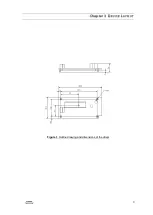
Page 7: ...3 Chapter 3 DEVICE LAYOUT Figure 1 Outline drawing and dimensions of the driver ...

Page 8: ...en in top view of the driver Port 1 Connector for DC power suppling and HV driving 1 1 Pin1 SYNC IN input 1 2 Pin2 GND 1 3 Pin3 DC power input 1 4 Pin4 N C 1 5 Pin5 GND 2 1 HV pulse output pin OUT 2 2 GND output pin 3 1 HV Power input pin 3 2 GND input pin from HV supply ...

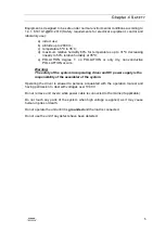
Page 9: ... dry non conductive POLLUTTION occurs Warning The safety of the system incorporating driver and HV power supply is the responsibility of the assembler of the system Operating the driver is allowed to persons acquainted with the operation manual and having permission to deal with voltages over 1000 V Do not remove unit covers while power cable is connected to the mains if applicable Do not touch an...

Page 10: ...ce EMI Please ensure proper wiring and grounding to avoid problems caused by interference The best solution to minimize EMI is to mount the driver and the HV power supply on the metal body of the laser The driver base plate must have very good contact with the ground wire of the HV power supply such as the four mounting holes on the edges of the board If the EMI level is still very high attempt mo...

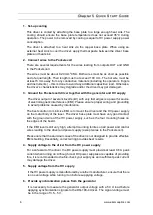
Page 11: ...7 After the generator output voltage is measured remove the 50 load and provide synchronization pulses to the driver Figure 3 Input circuit of driver Figure 4 Control timing charts ...

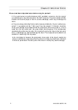
Page 12: ...the 1 M input Then the isolated 1 10 divider should be slowly and carefully moved towards the hot output wire When the probe is 10 mm away from the hot output wire the pulse shape should appear in the oscilloscope amplitude should be several volts Do not place the probe too close to the hot output wire a discharge may start and damage the driver This measurement method is not suitable for measurin...

Reviews: