background image

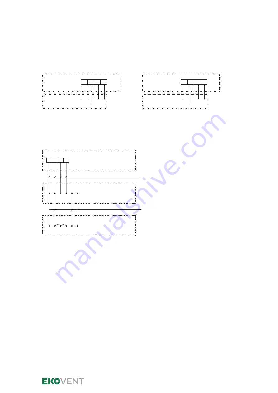
Connection example for Monitoring system EKO-KE2

EKO-KE2
Monitoring unit

Damper motor 24 V

16  17  18  19 

1

S4

2

S1


  S2  S6

Inkopp Ex KE2 Spj1_2011

EKO-KE2
Monitoring unit

Damper motor 24 V

20  21  22  23 

1

S4

2

S1


  S2  S6

Inkopp Ex KE2 Spj2_2011

EKO-KE2

Damper motor 24 V

Damper motor 24 V

16 17 18 19

1

2

S2 S6

4-conductor cable

4-conductor cable

S1

1

2

S4 S2 S6

S1 S4

2 dampers

Series connection, example

Damper 1

Damper 2

Damper group 1

2020-03

4 (5)

EKOVENT AB, Mejselgatan 7, SE-235 32 Vellinge, Sweden
Tel +46 40 42 16 00, [email protected], www.ekovent.com

Summary of Contents for EKO-KE2

Page 1: ...ee page 3 Automatic performance testing time The EKO KE2 control and monitoring system perfor mance tests connected dampers 10 hours after the unit has been supplied with voltage or after the manual test has been conducted the unit is then performance tested every 48 hours This displacement is to avoid performance testing taking place during the daytime The option to conduct performance testing at...

Page 2: ...ashing Operation power on Red 2 Non flashing Fire alarm Yellow 3 Non flashing Detector loop error Yellow 3 Flashing Damper error Red Yellow 2 3 Flashing Service alarm detector Green 4 Non flashing Normal mode Red 5 Non flashing Alarm mode Red Yellow Green 1 2 3 Non flashing Night closing dampers When the system is starting up EKO KE2 detects which damper inputs are connected EKO KE2_2011 measure 1...

Page 3: ...tor is present even if it is not selected In such case flashes red and yellow even during startup 2 Night closing Connected Disconnected 14 15 Alarm input 2 If night closing is not selected no jumper is required at the input If night closing is activated both red and yellow light Concluded with a manoeuvring operation 3 Post cooling Connected Disconnected 4 5 Releases buzzer alarm 1 seven minutes ...

Page 4: ...er motor 24 V 20 21 22 23 1 S4 2 S1 S2 S6 Inkopp Ex KE2 Spj2_2011 EKO KE2 Damper motor 24 V Damper motor 24 V 16 17 18 19 1 2 S2 S6 4 conductor cable 4 conductor cable S1 1 2 S4 S2 S6 S1 S4 2 dampers Series connection example Damper 1 Damper 2 Damper group 1 2020 03 4 5 EKOVENT AB Mejselgatan 7 SE 235 32 Vellinge Sweden Tel 46 40 42 16 00 info ekovent se www ekovent com ...

Page 5: ...gsexempel EKO KE2 kanaldetektor EKO RE i serie EKO RE Channel detector 2 1 5 6 7 2 2 kOhm EKO RE Channel detector 2 1 5 6 7 EKO RE Channel detector 2 1 5 6 7 EKO RE Channel detector 2 1 5 6 7 24 VAC separate supply for any auxiliary fan Smoke detectors connected in series When several smoke detectors are connected in series a terminating resistor must only be fitted to the last detector in the loo...

Reviews: