background image

2. Cable Connection and Screen Adjustment

1

3


Connect the power cord to the power connector on the rear of the 
monitor.

4


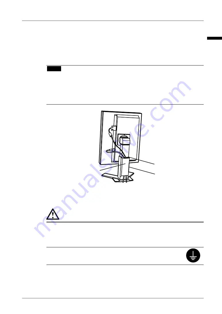
Thread the power cord and signal cable through the cable holder on 
the rear of the monitor stand.

NOTE

When threading the cables through the cable holder, lead them to the cable 

entrance side and pinch the projection to open the cable entrance.

It is recommended that some slack be left in the cables to allow for smooth 

adjustment of the monitor stand and easy rotation between the portrait and 
landscape positions.

5


Connect the other end of the power cord to a power outlet.


WARNING 

Use the enclosed power cord and connect to the standard power 
outlet of your country.
Be sure to remain within the rated voltage of the power cord. Not do-
ing so may result in fire or electric shock. 
The equipment must be connected to a grounded main outlet.
Not doing so may result in fire or electric shock. 

6


Turn on the monitor's power by touching the power switch.

The monitor’s power indicator will light up green.

Projection

Cable entrance

Cable holder

English

Summary of Contents for RadiForce RX211

Page 1: ...Wichtig Bitte lesen Sie diese Bedienungsanleitung sorgf ltig durch um sich mit dem sicheren und rationellen Betrieb dieses Produkts vertraut zu machen Bewahren Sie das vorliegende Handbuch zu Referen...

Page 2: ...erence to radio communications However there is no guarantee that interference will not occur in a particular installation If this equipment does cause harmful interference to radio or television rece...

Page 3: ...It shall be assured that the final system is in compliance to IEC60601 1 1 requirements English...

Page 4: ...al system or transmitted in any form or by any means electronic mechanical or otherwise without the prior written permission of EIZO NANAO CORPORATION EIZO NANAO CORPORATION is under no obligation to...

Page 5: ...g Two PCs to the Monitor 17 2 4 Screen Adjustment Analog Input 18 3 Adjustment and Settings 21 3 1 How to use the ScreenManager 21 3 2 ScreenManager menu 22 3 3 CAL Switch Function 27 3 4 Adjustment L...

Page 6: ...se read this section and the caution statements on the unit refer to the figure below Location of the Caution Statements Symbols on the unit Symbol Location This symbol indicates Rear Main power switc...

Page 7: ...age If an object or liquid falls spills into the cabinet unplug the unit immediately Have the unit checked by a qualified service engineer before using it again Place the unit at the strong and stable...

Page 8: ...supply 100 120 200 240 Vac 50 60Hz Do not overload your power circuit as this may result in fire or electric shock Handle the power cord with care Do not place the cord underneath the unit or other h...

Page 9: ...injury or equipment damage Do not block the ventilation slots on the cabinet Do not place any objects on the ventilation slots Do not install the unit in a closed space Do not use the unit laid down o...

Page 10: ...g is recommended to keep the monitor looking new and to prolong its operation lifetime Refer to Cleaning on the next page The screen may have defective pixels These pixels may appear as slightly light...

Page 11: ...a dry cloth for better finishing Tips Optional ScreenCleaner is recommended for cleaning the panel surface Cabinet To remove stains wipe the cabinet with a soft lightly moistened cloth using a mild d...

Page 12: ...iCS LE for Windows used to calibrate the monitor is included refer to the EIZO LCD Utility Disk The utility software ScreenManager Pro for Medical for Windows to control the monitor from a PC with mou...

Page 13: ...decreases adjusted values for advanced adjustments using the Adjustment menu p 21 5 Power Switch Turns the power on or off 6 Power indicator 2 Indicates monitor s operation status Green Orange Flashi...

Page 14: ...a peripheral USB device 11 Security lock slot Allows for connection of a security cable This lock supports Kensington s MicroSavere security system 12 Stand 3 Used to adjust the height and angle of th...

Page 15: ...Landscape 640 x 480 VGA 60 Hz 162 MHz Max 720 x 400 VGA TEXT 70 Hz 800 x 600 VESA 60 Hz 1024 x 768 VESA 60 Hz 1280 x 1024 VESA 60 Hz 1600 x 1200 VESA 60 Hz 1200 x 1600 Portrait Display 60 Hz Analog In...

Page 16: ...nd of the cable into the video connector on the PC After connecting secure the cable connectors with the attached screw in fasteners Digital Input Connect to SIGNAL1 DVI D Connector Signal Cable Conne...

Page 17: ...smooth adjustment of the monitor stand and easy rotation between the portrait and landscape positions 5 Connect the other end of the power cord to a power outlet WARNING Use the enclosed power cord a...

Page 18: ...signal it displays the image correctly based on its pre setting data When finished turn off the PC and the monitor Tips Adjust the brightness of the screen depending on the brightness of your environ...

Page 19: ...n the case of only one signal being present at either input the monitor automatically detects and displays that signal Priority Setting Performance 1 DVI D Connector The monitor gives preference to Si...

Page 20: ...unction begins showing a running status message to adjust clock phase display position and resolution automatically NOTE The Auto Adjustment function is intended for use on the Macintosh and on AT com...

Page 21: ...ing on the PC 3 The screen position is not incorrect Use the Position adjustment The correct displayed position of the monitor is decided because the number and the position of the pixels are fixed Th...

Page 22: ...nd adjust the horizontal resolution using the Right and Left Switches 3 Adjust the output signal range Dynamic Range of the signal Use the Range Adjustment p 45 of Screen menu This controls the level...

Page 23: ...3 2 ScreenManager menu p 22 CAL Switch menu Mode Switch 3 3 CAL Switch Function p 27 Switches Adjustment Lock Enter Switch Power Switch 3 4 Adjustment Lock Function p 28 For information about each fu...

Page 24: ...7 Screen Clock 2 4 Screen Adjustment p 18 Phase Position Resolution Range Adjustment Signal Filter Color 1 Brightness 4 1 Color Adjustment p 29 Temperature Gamma Saturation Hue Gain 6 Colors Reset Pow...

Page 25: ...enter switch Making adjustments and settings 1 Select the desired submenu icon with the directing switches and touch the enter switch 2 Select the desired setting icon with the directing switches and...

Page 26: ...ager Setup menu 2 Select Disable 3 Restart your computer NOTE If the orientation is changed while the computer is running the screen will be displayed correctly once the computer is restarted Mode Pre...

Page 27: ...ower saving mode Digital input This monitor complies with the DVI DMPM p 44 How to set 1 Set the PC s power saving settings 2 Select DVI DMPM in the PowerManager menu Power saving system PC Monitor Po...

Page 28: ...ng time Advance Notice 1 Flashing green Operating time expired Power off Flashing orange slowly 1 By touching the power switch on the control panel during the Advance Notice period the operating time...

Page 29: ...e Touch the mode switch while the CAL Switch menu is displayed Touching the mode switch allows you to select the following mode 1 DICOM 2 CUSTOM 3 CAL 4 TEXT 1 DICOM Making color adjustments in CAL Sw...

Page 30: ...itch How to lock 1 Turn off the monitor power by touching the power switch 2 Touch the power switch while touching the enter switch How to unlock 1 Turn off the monitor power by touching the power swi...

Page 31: ...re 1 Gamma 1 Saturation Hue Gain 6 colors Reset 1 These settings can also be adjusted on the CAL Switch menu p 27 2 When calibration is performed in this mode using the calibration kit RadiCS LE see O...

Page 32: ...Saturation To change the saturation 100 100 Selecting the minimum level 100 makes the image monochrome NOTE The Saturation adjustment may cause undisplayable color tone Hue Sets the hue value for fle...

Page 33: ...mages may appear distorted Enlarged Enlarges the image on the screen regardless of the image s resolution Since the vertical resolution and horizontal resolution are enlarged at same rates some horizo...

Page 34: ...ack area surrounding the displayed image Procedure 1 Select Border Intensity in the ScreenManager Others menu 2 Make adjustments with the Left and Right directing switches The Left directing switch ma...

Page 35: ...rt Using the USB Rev 2 0 compatible PC or peripherals is recommended If the monitor is in the power saving mode or if the monitor is connected to the power outlet with the monitor turned off all the d...

Page 36: ...o use RadiCS LE for Windows or ScreenManager Pro for Medical for Windows Refer to the corresponding User s Manual on the CD ROM disk in order to install and use the software When using the above softw...

Page 37: ...tand and attaching equipment such as a cable T V GS approved arm or stand Please connect cables after attaching an arm stand Setup Procedure 1 Hold the upper and lower centers of the stand joint cover...

Page 38: ...ch RGB adjusting value in Gain to higher level p 30 Indicator status Flashing orange slowly Try touching the power switch to turn it on again Indicator status Flashing orange quickly Try touching the...

Page 39: ...ing the same image for a long time 6 The screen has defective pixels e g slightly light or dark This is due to the characteristics of the panel itself and not the LCD product 7 Interference patterns o...

Page 40: ...nothing left on the face of Enter switch Wipe the control panel and then touch the Enter switch again with dry finger Make sure not to wear gloves Remove any gloves and try touching the switches again...

Page 41: ...temperature equipment is not located nearby Contact an EIZO dealer when the power switch fails to restart the monitor even after its location is moved NOTE Do not block the ventilation slots on the ca...

Page 42: ...Without USB load Less than 3W for single signal input without USB load 0W Input Connector DVI D D sub mini 15pin Analog Input Signal Sync Separate TTL Positive Negative Composite TTL Positive Negativ...

Page 43: ...376 14 8 13 2 0 52 62 5 2 46 92 3 62 25 0 98 33 1 3 SWIVEL Default Settings CAL Switch Mode The default display mode setting is 1 DICOM mode Brightness Color Temperature Gamma 1 DICOM 300cd m2 approx...

Page 44: ...ZO RP 902 Arm Stand EIZO LS HM1 D Dual Height Adjustable Stand EIZO LA 131 D LCD Monitor Flexible Arm EIZO LA 030 W Wall Mount Arm for LCD Monitor EIZO LA 011 W Wall Mount Arm for LCD Monitor Graphics...

Page 45: ...ld 7 DDC Data SDA 15 Ground return for 5V Hsync and Vsync 23 T M D S Clock 8 NC 16 Hot Plug Detect 24 T M D S Clock NC No Connection D Sub mini 15 pin Connector 5 1 3 4 2 8 7 6 9 10 12 13 14 15 11 Pin...

Page 46: ...l signal input only The other is DVI I connector for both digital and analog signal inputs DVI DMPM DVI Digital Monitor Power Management The Power management system for the digital interface The Monit...

Page 47: ...ures the white tone appears somewhat Green while at lower temperatures it appears somewhat red Computer monitors generally give best performance at high temperature settings 5000 K Slightly reddish wh...

Page 48: ...stment menu HINWEIS Je nach angeschlossenem PC kann die Anzeigeposition variieren sodass Justierungen mithilfe des Justierungsmen s erforderlich sein k nnen Wird ein Eingangssignal verwendet das in de...

Page 49: ...MHz Posi Posi 46 88 75 00 VESA 800 600 85Hz 56 3 MHz Posi Posi 53 67 85 06 VESA 1024 768 60Hz 65 0 MHz Nega Nega 48 36 60 00 VESA 1024 768 70Hz 75 0 MHz Nega Nega 56 48 70 07 VESA 1024 768 75Hz 78 8...

Page 50: ...tion electromagnetic immunity The RadiForce series are intended for use in the electromagnetic environment specified below The customer or the user of the RadiForce series should assure that it is use...

Page 51: ...ce series are intended for use in an electromagnetic environment in which radiated RF disturbances are controlled The customer or the user of the RadiForce series can help prevent electromagnetic inte...

Page 52: ...Befestigung des Standfusses mu derart erfolgen da die oberste Zeile der Bildschirmanzeige nicht h her als die Augenh he eines Benutzers in sitzender Position ist c Im Fall eines stehenden Benutzers mu...

Page 53: ...431 5011 Fax 1 562 431 4811 EIZO EUROPE AB Lovangsvagen 14 194 61 Upplands V sby Sweden Phone 46 8 594 105 00 Fax 46 8 590 91 575 EIZO NANAO AG Moosacherstrasse 6 Au CH 8820 W denswil Switzerland Phon...

Reviews: