background image

English


4. 

ADJUSTMENT 

21

NOTE 

x

More precise adjustment is available for using the “Screen Adjustment 
program” utility software.  It can be downloaded from the EIZO homepage 
(http://www.eizo.com/).    

3.

Adjust by using <Screen> menu in the ScreenManager. 

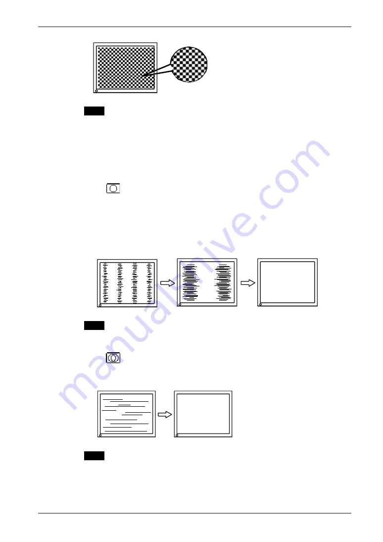
(1)  Vertical bars appear on the screen 

ĺ

 Use the <Clock> (p.40) adjustment. 

Select the “Clock” and eliminate the vertical bars by using the right and left of 
the control buttons. Do not continuously press the control buttons, as the 
adjustment value will change quickly and make it difficult to locate the most 
suitable adjustment point. 
If the horizontal flickering, blur or bars appear, proceed to “Phase” adjustment 
as follows. 


NOTE 

x

When adjusting the <Clock>, the horizontal screen size will also change. 

(2)  Horizontal flickering, blurring or bars appear on the screen. 

ĺ

 Use the <Phase> (p.40) adjustment. 

Select the <Phase> and eliminate the horizontal flickering, blurring or bars by 
using the right and left buttons. 


NOTE

x

Horizontal bars may not completely disappear from the screen depending on 
the PC. 

Summary of Contents for RadiForce G11-S

Page 1: ...User s Manual Monochrome LCD Monitor It shall be assured that the final system is in compliance to IEC60601 1 1 requirements...

Page 2: ...Microsoft Corporation PowerManager and RadiCS are trademarks of EIZO NANAO CORPORATION RadiForce ScreenManager and EIZO are registered trademarks of EIZO NANAO CORPORATION in Japan and other countrie...

Page 3: ...Useful Functions 18 4 ADJUSTMENT 20 4 1 Screen Adjustment 20 7 TROUBLESHOOTING 31 8 CLEANING 35 9 SPECIFICATIONS 36 10 GLOSSARY 40 MEMO 42 1 3 Controls Connectors 10 2 CABLE CONNECTION 12 2 1 Before...

Page 4: ...n and the caution statements on the unit refer to the figure below Location of the Caution Statements IN Symbols on the unit Symbol Location This symbol indicates Top Main power switch Press to turn t...

Page 5: ...f an object or liquid falls spills into the cabinet unplug the unit immediately Have the unit checked by a qualified service engineer before using it again Place the unit at the strong and stable plac...

Page 6: ...circuit as this may result in fire or electric shock Handle the power cord with care Do not place the cord underneath the unit or other heavy objects Do not pull on or tie the cord If the power cord b...

Page 7: ...injury When handling the unit grip the bottom of the unit firmly with both hands ensuring the panel faces outward before lifting Dropping the unit may result in injury or equipment damage OK Do not bl...

Page 8: ...els may appear as slightly light or dark area on the screen This is due to the characteristics of the panel itself and not the product The backlight of the LCD panel has a fixed life span When the scr...

Page 9: ...olor video signal compatibility x Auto Adjustment compliant x USB Universal Serial Bus hub supported p 27 x The height adjustable stand incorporated x Ultra slim bezel incorporated x The Portrait Land...

Page 10: ...Operation Orange Power saving Flashing orange 2 times for each Power save mode Digital only Flashing orange slowly Power is off Main power is on Off Power off 1 Select color or monochrome for the gra...

Page 11: ...LCD monitor has the capability of the Portrait Landscape display The panel pivots in the counter clockwise direction 90q The LCD monitor can be used with an optional arm stand by removing the stand s...

Page 12: ...into the computer without any manual settings Analog Input Resolution Frequency Dot Clock Remarks 640 480 85 Hz VGA VESA 720 400 70 Hz VGA TEXT 800 600 85 Hz VESA 832 624 75 Hz Apple Macintosh 1024 7...

Page 13: ...in fasteners Analog Input Signal Cable Connector PC Signal Cable FD C16 enclosed Video Output Connector D Sub mini 15 pin Analog graphics board BNC cable BNC connection is available when using the op...

Page 14: ...C35 FD C39 enclosed Video Output Connector DVI Monochrome digital graphics board NOTE x Only TMDS DATA1 Green of video signal data is displayed x The monitor is not compatible with a color digital gra...

Page 15: ...s power indicator will light up green If an image does not appear refer to the 7 TROUBLESHOOTING p 31 for advice Whenever finished turn off the PC and the monitor NOTE x When turning on the monitor th...

Page 16: ...select the desired setting icon and push the Enter button The setting menu appears 3 Use the Control buttons to make all required adjustments and push the Enter button to save the settings 3 Exiting...

Page 17: ...on or off p 18 Menu Size Change the size of the menu Menu Position Adjust the menu position Menu Off Timer Set the menu displaying time Menu Settings Translucent Set the transparency of the backgroun...

Page 18: ...reduce afterimage p 41 characteristics that are particular to LCD monitors when the monitor screen is left on for a long period without use Procedure 1 Select Off Timer in the ScreenManager Others me...

Page 19: ...tically locked Locked function x Brightness adjustment including the adjustment by left and right buttons on the front panel x Range adjustment x LUT Setting x Signal selection button Color Monochrome...

Page 20: ...d remains on the screen for 5 seconds While the message is on the screen push the Auto adjustment button again to automatically adjust the clock phase screen position and resolution If you do not wish...

Page 21: ...not continuously press the control buttons as the adjustment value will change quickly and make it difficult to locate the most suitable adjustment point If the horizontal flickering blur or bars appe...

Page 22: ...Position adjustment return to Clock adjustment and repeat the previously explained adjustment procedure Clock Phase Position 4 Screen image is smaller or larger than the actual screen images Use the...

Page 23: ...changing the brightness of the backlight Select Brightness in the Screen menu and adjust by using the right and left buttons NOTE x Directly pressing the control buttons also adjusts the brightness Pr...

Page 24: ...picture on the screen in full irrespective of the picture s resolution Since the vertical resolution and horizontal resolution are enlarged at same rates some horizontal or vertical image may disappea...

Page 25: ...the black area surrounding the displayed image Set the Border Intensity In the Enlarge mode or Full Screen mode the outer area border is usually black Select Border Intensity in the Others menu and ad...

Page 26: ...r saving mode Analog input This monitor complies with the VESA DPMS p 41 Procedure 1 Set the PC s power saving settings 2 Select VESA DPMS in the PowerManager menu Power saving system PC Monitor Power...

Page 27: ...cturer of each device about the USB support When the monitor is not on the peripherals connected to the downstream ports will not operate Even if the monitor is in a power saving mode the devices conn...

Page 28: ...s USB hub is available for connecting USB compliant peripherals to the downstream ports of the monitor Connecting Examples PC Keyboard Printer Mouse Downstream Downstream ports Connect the cables fro...

Page 29: ...ortable Weight Total weight of the monitor without stand and attaching equipment such as a cable T V GS approved arm or stand x Please connect cables after attaching an arm stand Setup Procedure 1 Piv...

Page 30: ...English 30 6 ATTACHING AN ARM STAND 4 Mounting Screws M4 x 15 mm BZn Fe Arm stand...

Page 31: ...ange twice for each Check the Brightness settings Try pressing a key on the keyboard or clicking the mouse p 26 Try pressing the power button Try turning the PC on 2 Error messages shown below will re...

Page 32: ...crease the vertical bars using the Clock p 21 6 Horizontal bars of distortion appear Decrease the horizontal bars using the Phase p 21 7 Letters and lines appear blurred Adjust the blurred lines using...

Page 33: ...l the time p 18 12 The screen has defective pixels e g slightly light or dark This is due to the characteristics of the panel itself and not the LCD product 13 Fingerprints remain on the screen Leavin...

Page 34: ...correctly connected Check that the PC and OS are USB compliant For verification of USB support consult the manufacturer of each system Check the PC s BIOS setting for USB For details refer to the man...

Page 35: ...as these may cause damage to the cabinet or LCD panel Cabinet To remove stains wipe the cabinet with a soft lightly moistened cloth using a mild detergent Do not spray wax or cleaner directly into the...

Page 36: ...an 8 W When the USB hub are not connected Input Connector DVI I x 1 a Separate TTL Positive Negative b Composite TTL Positive Negative Analog Input Signal Sync c Sync on Green 0 3 Vp p Negative Analog...

Page 37: ...ss A Classification of medical device Class I Dimensions Default settings Analog input Digital input Signal Selection Color Smoothing 3 PowerManager VESA DPMS DVI DMPM Screen Size Normal Off Timer Dis...

Page 38: ...1 Analog Red 6 DDC Clock SCL 16 Hot Plug Detect C2 Analog Green 7 DDC Data SDA 17 TMDS Data0 C3 Analog Blue 8 Analog Vertical Sync 18 TMDS Data0 C4 Analog Horizontal Sync 9 TMDS Data1 19 TMDS Data0 5...

Page 39: ...7 50 75 00 Nega Nega VESA 640 480 36 0 43 27 85 01 Nega Nega VESA 800 600 36 0 35 16 56 25 Posi Posi VESA 800 600 40 0 37 88 60 32 Posi Posi VESA 800 600 50 0 48 08 72 19 Posi Posi VESA 800 600 49 5 4...

Page 40: ...and analog signal inputs DVI DMPM DVI Digital Monitor Power Management The Power management system for the digital interface The Monitor ON status operation mode and the Active Off status power saving...

Page 41: ...l pixels are displayed as a full screen TMDS Transition Minimized Differential Signaling A signal transition method for the digital interface VESA DPMS Video Electronics Standard Association Display P...

Page 42: ...English 42 MEMO MEMO...

Page 43: ...Bey dem ger t handelt es sich um ein Klasse A Produkt Bei Betrieb des Ger ts in Wohnumgebungen ist gegebenenfalls durch entsprechende Ma nahmen daf r zu sorgen dass eine St rung des Radio und Fernsehe...

Page 44: ......

Reviews: