background image

24

4. ADJUSTMENT

(3) The screen position is incorrect.

Æ

Æ

Æ

Æ

Æ

Use the “Position” adjustment.

The correct displayed position of LCD monitor is decided because the number
and the position of the pixels are fixed.  The “Position” adjustment moves the
image to the correct position.

Select “Position” and adjust the position of the upper left corner of the image
by using the up, down, right and left buttons in order to align the screen.

If vertical bars of distortion appear after finishing the “Position” adjustment,
return to “Clock” adjustment and repeat the previously explained adjustment
procedure (“Clock”

Æ

 “Phase” 

Æ

“Position”).

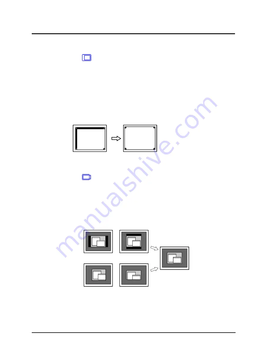
(4) Screen image is smaller or larger than the actual screen images.

Æ

Æ

Æ

Æ

Æ

Use the “Resolution” adjustment.

Adjustment is needed when the input signal resolution and the resolution now
being displayed is different.
Select “Resolution” and confirm if the resolution now being displayed is the
same as the input resolution.  If it is not, adjust the vertical resolution using
the up and down button and adjust the horizontal resolution using the right
and left buttons.

Adjusted to actual screen

Smaller than the actual screen images.

Larger than the actual screen images.

Summary of Contents for FlexScan L675

Page 1: ...ENGLISH ENGLISH ...

Page 2: ...ubmitted material or information confidential unless prior arrangements are made pursuant to Eizo Nanao Corporation s receipt of said information Although every effort has been made to ensure that this manual provides up to date information please note that EIZO monitor specifications are subject to change without notice ENERGY STAR is a U S registered mark Apple and Macintosh are registered trade...

Page 3: ...1 How to use the ScreenManager 18 3 2 ScreenManager Adjustments and Settings 19 3 3 Useful Functions 20 4 ADJUSTMENT 22 4 1 Screen Adjustment 22 4 2 Displaying the low resolutions 27 4 3 Color adjustment 29 4 4 Power save Setup 31 5 MAKING USE OF USB Universal Serial Bus 33 6 CONNECTING TWO PCs to THE MONITOR 35 7 ATTACHING AN ARM STAND 37 8 TROUBLE SHOOTING 39 9 CLEANING 43 10 SPECIFICATIONS 44 1...

Page 4: ... service personnel Do not attempt to service this product yourself as opening or removing covers may expose you to dangerous voltage or other hazards IMPORTANT This product has been adjusted specifically for use in the region to which it was originally shipped If operated outside the region to which it was originally shipped the product may not perform as stated in the specifications To ensure per...

Page 5: ...d service engineer before using it again Using a unit after it has been dropped may result in fire or electric shock Set the unit in an appropriate location Not doing so may cause damage and could result in fire or electric shock Do not place in outdoors Do not place in the transportation system ship aircraft trains automobiles etc Do not install in a dusty or humid environment Do not place in a l...

Page 6: ...l outlet Not doing so may result in fire or electric shock Handle the power cord with care Do not place the cord underneath the unit or other heavy objects Do not pull on or tie the cord If the power cord becomes damaged stop using it Use of a damaged cord may result in fire or electric shock Never touch the plug and power cord if it begins to thunder Touching them may result in electric shock Whe...

Page 7: ...onal i Sound sound unit if applicable when moving the unit Moving the unit with the cord attached is dangerous It may result in injury or equipment damage When handling the unit grip the bottom of the unit firmly with both hands ensuring the panel faces outward before lifting Then do not grasp the LCD panel Dropping the unit may result in injury or equipment damage Do not block the ventilation slo...

Page 8: ...e of a problem Periodically clean the area around the plug Buildup of dust water or oil on the plug may result in fire Unplug the unit before cleaning it Cleaning the unit while it is plugged into a power outlet may result in electric shock If you plan to leave the unit unused for an extended period disconnect the power cord from the wall socket after turning off the power switch for the safety an...

Page 9: ...e rest period each hour is suggested LCD Panel The screen may have defective pixels These pixels may appear as slightly light or dark area on the screen This is due to the characteristics of the panel itself and not the product The backlight of the LCD panel has a fixed life span When the screen becomes dark or begins to flicker please contact your dealer Do not press on the panel or edge of the f...

Page 10: ... scanning frequency of 50 85 Hz 1280 x 1024 75Hz Vertical Digital of 60Hz VGA text 70Hz Auto Adjustment compliant and original Picture Adjustment Program software included Smoothing function incorporated for the adjustment of an enlarged image ColorManagement function incorporated USB Universal Serial Bus hub supported The height adjustable stand incorporated Ultra slim bezel incorporated The Port...

Page 11: ... dealer for assistance if any of the listed items are missing or damaged LCD Monitor Power Cord Signal Cable Signal Cable FD C04 FD C16 EIZO LCD Utility Disk User s Manual Quick Reference Warranty Registration Card Please retain the packing materials for future transference ...

Page 12: ...Enter Button 5 Control Buttons 6 Power Button 7 Power Indicator 1 Indicated color Power on status Green Power is on Yellow Power save mode Flasing Yellow Power save mode Digital only Slowly flashingYellow Power is off Main power is on 8 ScreenManager 1 Regarding the power indicator for the Off Timer see page 21 2 5 6 7 8 3 4 1 ...

Page 13: ...it Landscape display For the Portrait display use the software for the portrait The LCD monitor can be used with an optional arm stand by removing the stand see page 37 3 Allows for connection of a security cable This lock supports Kensington s MicroSaver security system For further information please consult Kensington Technology Group 2855 Campus Drive San Mateo CA 94403 USA 800 650 4242 x3348 I...

Page 14: ...ile Digital Input Only the following resolutions with frequency can be displayed on this model n o i t u l o s e R y c n e u q e r F s k r a m e R 0 8 4 x 0 4 6 z H 0 6 A G V 0 0 4 x 0 2 7 z H 0 7 t x e T A G V 0 0 6 x 0 0 8 z H 0 6 A S E V 8 6 7 x 4 2 0 1 z H 0 6 A S E V 0 6 9 x 0 8 2 1 z H 0 6 A S E V 4 2 0 1 x 0 8 2 1 z H 0 6 A S E V n o i t u l o s e R y c n e u q e r F s k r a m e R 0 8 4 x 0...

Page 15: ...of the cable into the video connector on the PC After connecting secure the connection with the screw in fasteners FD C16 enclosed Macintosh Adapter Optional Video Output Connector D Sub mini 15 pin Standard graphics board Macintosh G3 Blue White G4 Macintosh Video Output Connector D Sub 15 pin FD C04 enclosed Video Output Connector DVI Digital graphics board Analog Input Digital Input Connectors ...

Page 16: ...to remain within the rated voltage of the power cord Not doing so may cause in fire or electric shock WARNING WARNING 3 Lead the power cord and signal cable into the cable holder at the rear of the monitor When housing the cables into the cable holder lead them to the cable entrance side and pinch the projection to open the cable entrance The cables are recommended to lead with slight sag for the ...

Page 17: ...PC s power Whenever finished turn off the PC and the monitor When turning on the monitor the kind of the input signal Signal 1 or 2 Analog or Digital is displayed for a few seconds on the right top corner of the screen The equipment must be connected to a grounded main outlet Not doing so may cause in fire or electric shock WARNING WARNING ...

Page 18: ...icon using the Control buttons and push the Enter button The sub menu appears 2 Use the Control buttons to select the desired setting icon and push the Enter button The setting menu appears 3 Use the Control buttons to make all required adjustments and push the Enter button to save the settings 3 Exiting the ScreenManager 1 To return to the main menu select the Return icon or push the down button ...

Page 19: ...Set the monitor s off timer to on or off p 21 Input Priority Select the priority signal p 36 Beep Set the Monitor s beeper to on or off p 45 Menu Settings Menu Size Change the size of the menu Menu Position Adjust the menu position Menu Off Timer Set the menu displaying time Translucent Set the transparency of the background Rotate Change the orientation of the ScreenManager Reset Return to the fa...

Page 20: ...off the monitor s power by the power button on the front panel then hold down the Auto adjustment button once again and turn the power back on EIZO Logo Disappearing function When switching on the power button on the front panel the EIZO logo is displayed for a while If you desire to undisplay this logo use this function To undisplay Switch off the monitor s power by the power button on the front ...

Page 21: ...r to LCD monitors when the monitor screen is left on for a long period without use Procedure 1 Select Off Timer in the ScreenManager Others menu 2 Select Enable and press the right and left buttons to adjust the On Period 1 to 23 hours Off timer system 1 Advance notice LED flashing green will be given 15 minutes before the monitor automatically enters the Power Off mode To delay entering the Power...

Page 22: ...sh the Auto adjustment button on the front panel The message Your setting will be lost if you press again now appears and remains on the screen for 5 seconds While the message is on the screen push the Auto adjustment button again to automatically adjust the clock phase screen position and resolution If you do not wish to do adjust the screen do not push the Auto adjustment button again If the app...

Page 23: ...hange quickly and make it difficult to locate the most suitable adjustment point If the horizontal flickering blur or bars appear proceed to Phase adjustment as follows When adjusting the Clock the horizontal screen size will also change 2 Horizontal flickering blurring or bars appear on the screen Æ Æ Æ Æ Æ Use the Phase p 47 adjustment Select the Phase and eliminate the horizontal flickering blu...

Page 24: ...tion adjustment return to Clock adjustment and repeat the previously explained adjustment procedure Clock Æ Phase Æ Position 4 Screen image is smaller or larger than the actual screen images Æ Æ Æ Æ Æ Use the Resolution adjustment Adjustment is needed when the input signal resolution and the resolution now being displayed is different Select Resolution and confirm if the resolution now being displ...

Page 25: ...ng the control buttons directly adjusts the range automatically 5 Set the Contrast of the screen Æ Æ Æ Æ Æ Use the Contrast adjustment This controls the brightness for the each color red blue and green at a same time Select Contrast Brightness in the screen menu and adjust by using the right and left buttons Percentage over the 100 may cause undisplayable color tone 6 Set the Brightness of the scr...

Page 26: ...djustment items using the Screen menu of the ScreenManager 1 The screen position is incorrect Æ Æ Æ Æ Æ Use the Position adjustment See page 24 2 Screen image is smaller or larger than the actual screen images Æ Æ Æ Æ Æ Use the Resolution adjustment See page 24 3 Set the Contrast of the screen Æ Æ Æ Æ Æ Use the Contrast adjustment See page 25 4 Set the Brightness of the screen Æ Æ Æ Æ Æ Use the Br...

Page 27: ... picture s resolution Since the vertical resolution and the horizontal resolution are enlarged at different rates some images may appear distorted Enlarged Displays the picture on the screen in full irrespective of the picture s resolution Since the vertical resolution and horizontal resolution are enlarged at same rates some horizontal or vertical image may disappear Normal Displays the picture a...

Page 28: ...d in the following resolution 1280 x 1024 The image size is doubled both in horizontally and vertically i e 1280 x 960 enlarged from 640 x 480 to provide clear focus which does not require this function 3 Set the brightness of the black area surrounding the displayed image Æ Æ Æ Æ Æ Set the Border Intensity In the Enlarged mode or Full Screen mode the outer area border is usually black Select Bord...

Page 29: ...n the percentages for each will probably not be the same In the analog input perform the Range Adjustment p 25 before making the color adjustments The gradation pattern like below is recommended for the Range Adjustment 1 To change the color tone of the white Æ Æ Æ Æ Æ Set the Temperature p 46 The Temperature can be set from 4 000 K to 10 000 K in 500 K increments including 9 300 K The default set...

Page 30: ...e selected from 20 to 20 To register the adjustment select the Save icon and then push the enter button The Hue adjustment may cause undisplayable color tone 4 To adjust each color red green and blue Æ Æ Æ Æ Æ Use the Gain p 47 adjustment By adjusting the red green and blue color tones for each mode custom colors can be defined The 100 indicates unadjusted condition Display a white or gray backgro...

Page 31: ...creen like Blank Screen ScreenSaver software 1 To use the PC s power saving system VESA DPMS Procedure 1 Set the PC s power saving settings 2 Select VESA DPMS in the PowerManager menu Power saving system Operate the mouse or keyboard to return to a normal screen 2 To set the power save with ScreenSaver software EIZO MPMS Procedure 1 Set the PC s appropriate ScreenSaver settings or blank the screen...

Page 32: ...e PC s off mode is only supported when Manual is selected on the ScreenManager s Input Priority Operate the mouse or keyboard to return to a normal screen from the Power save mode of the PC Power on the PC to return a normal screen from the Off mode of the PC C P r o t i n o M D E L n O n o i t a r e p O n e e r G g n i v a s r e w o P g n i v a s r e w o P w o l l e Y e d o m f f O g n i v a s r ...

Page 33: ...ot on the peripherals connected to the downstream ports will not operate Even if the monitor is in a power saving mode the devices connected to the monitor s USB ports both the upstream and the downstream will function Connecting to the USB HUB Do not connect the downstream port of the monitor to any peripherals until finishing the USB function The followings are procedures for the Windows 98 Me 2...

Page 34: ... ports Connect the cables from USB compliant peripherals such as a mouse keyboard etc Printer Digital Camera Scanner Keyboard 3 After setting up the monitor s USB hub is available for connecting USB compliant peripherals to the downstream ports of the monitor Example of connection Keyboard Downstream Mouse ...

Page 35: ...utput Connector D Sub mini 15 pin Digital graphics board Video Output Connector DVI FD C04 enclosed FD C04 Optional 6 CONNECTING TWO PCs to THE MONITOR Two PCs can be connected to the monitor through the Signal 1 and the Signal 2 on the back of the monitor Connecting Examples Analog x Digital Analog x Analog Digital x digital Standard graphics board Video Output Connector D Sub mini 15 pin DVI I c...

Page 36: ... only one signal being present at either input the monitor automatically detects and displays that signal Priority setting Performance Signal 1 If signals from both inputs are present the monitor gives preference to Signal 1 in the following cases When the power of the monitor is turned ON When the signal input to Signal 1 is changed even if active input was Signal 2 Signal 2 If signals from both ...

Page 37: ...the arm mounting pad Use an arm stand that is able to support an object weighing 13 5 kg TÜV GS approved arm stand Use an arm stand with sufficient stability mechanical firmness to support the weight of the monitor Use an arm stand remaining that position where it is manually moved Use an arm stand with the ability to tilt the monitor forward and backward Please connect cables after attaching an a...

Page 38: ...rews Not doing so may cause the unit to come unattached which may result in injury or equipment damage When the unit is dropped please ask your dealer for advice Do not continue using a damaged unit Using a damaged unit may result in fire or electric shock When reattaching the tilt stand please use the same screws and tighten them securely WARNING WARNING For the Portrait display rotate the monito...

Page 39: ...g a key on the keyboard or clicking the mouse p 31 Try pressing the power button These messages appear when the signal is not inputted correctly even if the monitor functions properly Error messages shown below will remain on the screen for 40 seconds When the image is displayed correctly after a short time there is no problem with the monitor Some PCs do not output the signal soon after powering ...

Page 40: ...3 Adjust the blurred lines using Smoothing p 28 This happens when both composite X OR input signal and separate vertical synchronizing signal are input Please select one of the two Adjust the contrast and brightness The backlight of the LCD monitor has a fixed life span When the screen becomes dark or begins to flicker please contact your dealer When the screen image is changed after displaying th...

Page 41: ...22 The adjustment lock is probably on To unlock switch the LCD monitor off Then while pressing the Auto adjustment button switch the power on p 20 The Auto sizing function is intended for use on the Macintosh and on AT compatible PC running Windows It may not work properly in either of the following cases When running an AT compatible PC on MS DOS Not windows The background color for the wall pape...

Page 42: ...eripherals to other downstream ports If the problem is solved by doing this contact an EIZO dealer Try executing the following method Restarting the PC Connecting the PC and peripherals directly If the problem is solved by doing this contact an EIZO dealer The power button of the APPLE keyboard does not operate if it is connected to the EIZO USB Hub Please connect the keyboard directly with the PC...

Page 43: ...ther strong solvents as these may cause damage to the cabinet or LCD panel Cabinet To remove stains wipe the cabinet with a soft lightly moistened cloth using a mild detergent Do not spray wax or cleaner directly onto the cabinet LCD Panel The LCD surface can be cleaned with a soft cloth such as cotton or lens paper If necessary stubborn stains can be removed by moistening part of a cloth with wat...

Page 44: ...is not connected Input Connector DVI I x 2 Input Signal Sync a Separate TTL Positive Negative b Composite TTL Positive Negative c Sync on Green 0 3 Vp p Negative Video 0 7 Vp p 75 Ω Positive Digital TMDS Single Link Signal registration 28 Factory preset 23 Digital 5 Factory preset 0 Plug Play VESA DDC 2B Dimensions 399 mm W x423 5 mm H minimum x208 5 mm D 15 7 W x 16 7 H x 8 2 D Dimensions without...

Page 45: ...ry15 sec Monitor is in the advance notice mode of the Off Timer The power will be off within fifteen minutes u n e m r e g a n a M n e e r c S g o l a n A l a t i g i D t s a r t n o C 0 0 1 s s e n t h g i r B 0 0 1 g n i h t o o m S 3 t n e m e g a n a M r o l o C e d o M r o l o C d r a d n a t S e r u t a r e p m e T f f O r e g a n a M r e w o P S M P D A S E V M P M D I V D e z i S n e e r c...

Page 46: ...hat red Computer monitors generally give best perfoemance at high temerature settings 5000K Slightly reddish white 6500K Warm white tone similar to white papaer or daylight 9 300K Slightly bluish white DVI Digital Visual Interface A digital flat panel interface DVI can transmit digital data from the PC directly without loss with the signal transition method TMDS There are two kinds of DVI connecto...

Page 47: ...evel of output signal range to display the whole color gradation Resolution The LCD panel consists of a fixed number of pixel elements which are illuminated to form the screen image The EIZO L675 consists of 1280 horizontal pixels and 1024 vertical pixels At a resolution of 1280 X 1024 all pixels are used and the image is displayed as a full screen At the lower display modes of 640 x 480 or 800 x ...

Page 48: ...H Height Adjustable Stand 10 13 How to use the ScreenManager 18 Hue 19 30 I Information 19 Input Priority 19 36 L Language 19 M MAKING USE OF USB Universal Serial Bus 33 Menu Off Timer 19 Menu Position 19 O Off timer 19 21 Others 19 P Package Contents 11 Phase 19 23 47 Pin Assignment iv Position 19 24 26 Power consumption 44 Power Indicator 12 PowerManager 19 31 32 Power save Setup 31 PRECAUTIONS ...

Page 49: ...12 INDEX 49 ENGLISH U USB 10 31 33 44 V VESA DPMS 19 31 47 ...

Page 50: ...50 12 INDEX MEMO ...

Page 51: ... nachfolgenden Diagramme 23 signaux ont été enregistrés en usine dans le microprocesseur du moniteur conformément au diagramme de synchronisation ci dessous A Front Porch Vordere Schwarzschulter Front avant B Sync Period Synchronimpuls Délai de synchronisation C Back Porch Hintere Schwarzschulter Front arrière D Blanking Period Austastzeit Délai de clignotement E Display period Display Zeit Délai ...

Page 52: ...0 106 800 x 600 40 0 37 88 60 32 40 1 128 4 VESA 1 120 0 770 2 400 0 125 800 x 600 50 0 48 08 72 19 56 37 120 6 VESA 0 323 0 021 1 616 0 064 800 x 600 49 5 46 88 75 00 16 1 80 3 VESA 0 569 0 019 1 138 0 056 800 x 600 56 25 53 674 85 061 32 1 64 3 VESA 0 369 0 062 2 092 0 124 1024 x 768 65 0 48 36 60 00 24 3 136 6 VESA 0 320 0 053 1 813 0 106 1024 x 768 75 0 56 48 70 07 24 3 136 6 VESA 0 203 0 017 ...

Page 53: ...26 400 16 579 88 23 256 28 800 600 1056 628 1 280 0 478 4 800 1 373 16 000 12 480 20 800 13 853 64 23 240 66 800 600 1040 666 3 232 0 448 5 172 0 533 16 162 12 800 21 333 13 333 160 21 256 25 800 600 1056 625 2 702 0 503 4 409 0 578 14 222 11 179 18 631 11 756 152 27 248 31 800 600 1048 631 2 462 0 600 4 923 0 786 15 754 15 880 20 677 16 666 160 29 320 38 1024 768 1344 806 19 20 0 513 4 053 0 673 ...

Page 54: ...D g u l P t o H 2 C n e e r G g o l a n A 7 A D S a t a D C D D 7 1 0 a t a D S D M T 3 C e u l B g o l a n A 8 g o l a n A c n y S l a c i t r e V 8 1 0 a t a D S D M T 4 C g o l a n A c n y S l a t n o z i r o H 9 1 a t a D S D M T 9 1 5 0 a t a D S D M T d l i e h S 5 C d n u o r G g o l a n A B G R g o l a n a n r u t e r 0 1 1 a t a D S D M T 0 2 C N NC No Connection DVI I Connector USB ports...

Page 55: ...e labelling scheme was developed as a joint effort by the TCO The Swedish Confederation of Professional Employees Svenska Naturskyddsforeningen The Swedish Society for Nature Conservation and Statens Energimyndighet The Swedish National Energy Administration Approval requirements cover a wide range of issues environment ergonomics usability emission of electric and magnetic fields energy consumpti...

Page 56: ... in high doses The relevant TCO 99 requirement states that batteries the colour generating layers of display screens and the electrical or electronics components must not contain any cadmium Mercury Mercury is sometimes found in batteries relays and switches It damages the nervous system and is toxic in high doses The relevant TCO 99 requirement states that batteries may not contain any mercury It...

Page 57: ... t ma t ma t may cause y cause y cause y cause y cause undesir undesir undesir undesir undesired oper ed oper ed oper ed oper ed opera a a a ation tion tion tion tion This equipment has been tested and found to comply with the limits for a Class B digital device pursuant to Part 15 of the FCC Rules These limits are designed to provid reasonable protection against harmful interference in a resident...

Reviews: