background image

English 


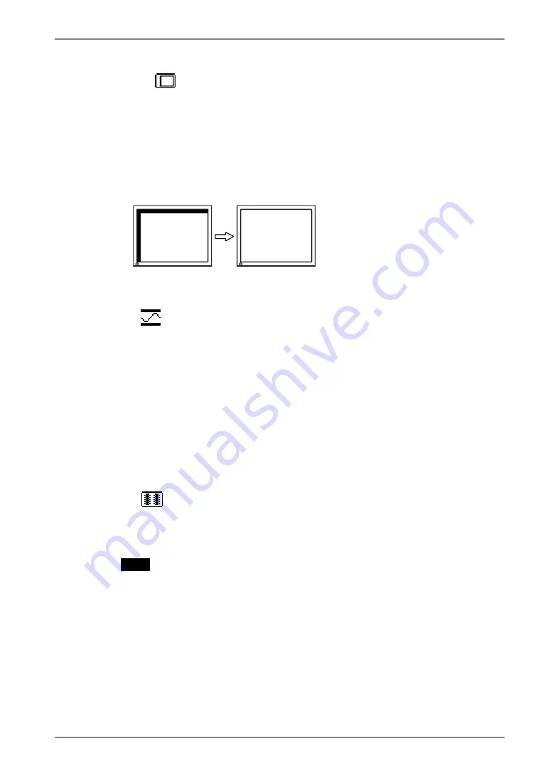
(3)  The screen position is incorrect. 


  Use the <Position> adjustment. 

The correct displayed position of the monitor is decided because the number 
and the position of the pixels are fixed. The “Position” adjustment moves the 
image to the correct position. 
Select <Position> and adjust the position by using the Up, Down, Right and 
Left Buttons. 
If vertical bars of distortion appear after finishing the <Position> adjustment, 
return to <Clock> adjustment and repeat the previously explained adjustment 
procedure. Clock

 Phase

 Position 


4. 

To adjust the output signal range (Dynamic Range) of the signal. 


  Use the <Range Adjustment> (p.42) of <Screen> menu. 

This controls the level of output signal range to display the whole color gradation 
(256 colors).  

 [Procedure] 

Press the Auto Adjustment Button on the control panel while displaying the 
<Range Adjustment> menu to automatically adjust the range. The screen blanks 
for a moment, and adjusts the color range to display the whole color gradation of 
the current output signal. 


5. 

To smooth the blurred texts of the enlarged screen of the lower 
resolutions.   


 Switch the <Smoothing> setting. 

<Smoothing> is clear-cut the letters or lines. 
Select <Smoothing> in the screen menu and select the suitable level from 1 ~ 5.  

NOTE


• 

The “Smoothing” is disabled in the resolution 1024 x 768. 

• 

Since the displayed image is enlarged, the blurred texts may not be 
necessarily lost completely. 


4. 

ADJUSTMENT 

23 

Summary of Contents for FlexScan L 353T L353T-C L353T-C

Page 1: ...User s Manual Touch Panel Color LCD Monitor It shall be assured that the final system is in compliance to IEC60601 1 1 requirements...

Page 2: ...cal or otherwise without the prior written permission of EIZO NANAO CORPORATION EIZO NANAO CORPORATION is under no obligation to hold any submitted material or information confidential unless prior ar...

Page 3: ...2 3 Connecting two PCs to the monitor 15 2 4 Sound Connections 16 3 ScreenManager 17 3 1 How to use the ScreenManager 17 3 2 Adjustments and Settings 18 3 3 Useful Functions 19 4 ADJUSTMENT 21 4 1 Sc...

Page 4: ...ns To ensure personal safety and proper maintenance please read this section and the caution statements on the unit refer to the figure below Location of the Caution Statements Symbols on the unit Sym...

Page 5: ...shock or equipment damage If an object or liquid falls spills into the cabinet unplug the unit immediately Have the unit checked by a qualified service engineer before using it again Place the unit on...

Page 6: ...e in fire or electric shock Use the correct voltage Do not overload your power circuit as this may result in fire or electric shock The unit is designed for use with a specific voltage only Connection...

Page 7: ...ase wash thoroughly If some physical symptoms result please consult your doctor CAUTION Handle with care when carrying the unit Disconnect the power cord and cables when moving the unit Moving the uni...

Page 8: ...sity use of a monitor in lower brightness is recommended The screen may have defective pixels These pixels may appear as slightly light or dark area on the screen This is due to the characteristics of...

Page 9: ...peaker system Touch Panel provided Touch Panel Pointer TP1 is available optional p 14 1 2 Package Contents Please contact your local dealer for assistance if any of the listed items are missing or dam...

Page 10: ...utton to display the volume control bar Press the Right or Left Button to mute off 3 SIG Input Signal Selection Button 4 Auto Adjustment Button AUTO 5 ENT Enter Button 6 Control Buttons Left Down Up R...

Page 11: ...or Mounting a stand 4 16 Stand Detachable 4 3 Allows for connection of a security cable This lock supports Kensington s MicroSaver security system For further inforamation please consult Kensington Te...

Page 12: ...function p 23 to make the lines clear When your computer and display support VESA DDC the suitable resolution and the refresh rate are set by just plugging your display into the computer without any m...

Page 13: ...connection with the screw in fasteners Analog Input Signal Cable Connector of PC PC Signal Cable enclosed MD C87 Video Output Connector D Sub mini 15 pin Input Connecor monitor D Sub mini 15 pin Stand...

Page 14: ...r electric shock 3 Turn on the monitor s main power and then switch on the PC s power The monitor s power indicator will light up blue If an image does not appear refer to the 6 TROUBLESHOOTING p 30 f...

Page 15: ...s A 10 minute rest period each hour is suggested 2 3 Connecting two PCs to the monitor Two PCs can be connected to the monitor through the DVI and the D Sub mini 15 pin connector on the back of the mo...

Page 16: ...rnal line in of the monitor 1 Connect the stereo mini jack cable to the external line in of the monitor 2 Connect the other side of stereo mini jack cable to the line out of audio devices POWER INPUT...

Page 17: ...on and press the Enter Button The setting menu appears 3 Use the Control Buttons to make all required adjustments and press the Enter Button to save the settings 3 Exiting the ScreenManager 1 To retur...

Page 18: ...A DPMS PowerManager Sound 4 3 Power save Setup p 27 Input Signal Set the input signal selection of automatic or manual p 20 Off Timer Set the power save p 19 VGA Selection Select the display mode p 31...

Page 19: ...function was created to reduce afterimage characteristics that are particular to LCD monitors when the monitor screen is left on for a long period without use Procedure 1 Select Off Timer in the Scre...

Page 20: ...splay again 1 Switch off the monitor s power by the Power switch 2 Hold down the Enter button once again and turn the power back on Automatically selecting the input signal function The monitor will a...

Page 21: ...on the control panel The message Your setting will be lost if you press again now appears and remains on the screen for 5 seconds While the message is on the screen press the Auto Adjustment Button ag...

Page 22: ...e the vertical bars by using the Right and Left of the Control Buttons Do not continuously press the Control Buttons as the adjustment value will change quickly and make it difficult to locate the mos...

Page 23: ...nge Adjustment p 42 of Screen menu This controls the level of output signal range to display the whole color gradation 256 colors Procedure Press the Auto Adjustment Button on the control panel while...

Page 24: ...een is controlled by changing the brightness of the backlight Select Brightness in the screen menu and adjust by using the Up and Down Buttons NOTE Directly pressing the Up and Down Buttons also adjus...

Page 25: ...ific adjustment They are available only as a reference tool To create an uniform white or black screen the percentages for each will probably not be the same Adjustment Contents Color Mode Menu Custom...

Page 26: ...may cause undisplayable color tone To change each color red green and blue 0 100 By adjusting the red green and blue color tones for each mode custom colors can be defined Display a white or gray bac...

Page 27: ...Power saving Yellow Power Resumption Procedure Operate the mouse or keyboard to return to a normal screen Digital Input This monitor complies with the DVI DMPM p 41 Procedure 1 Set the PC s power savi...

Page 28: ...en the monitor is in the power saving mode sound of speaker also erases simultaneously can be performed Procedure 1 Set the PC s power saving settings 2 Select Sound 3 Select Disable Enable is selecte...

Page 29: ...stand mounting 75 mm x 75 mm VESA compliant Supportable Weight Total weight of the monitor without stand and attaching equipment such as a cable T V GS approved stand Please connect cables after attac...

Page 30: ...ing the mouse p 27 Indicator status Flashing Yellow twice for each Try pressing the power of the computer 2 The message below appears This message appears when no signal is input This is displayed for...

Page 31: ...e Clock p 22 5 Horizontal bars of distortion appear Decrease the horizontal bars using the Phase p 22 6 Letters and lines appear blurred Switch the Smoothing mode p 23 7 The screen is too bright or to...

Page 32: ...CD monitor off Then while pressing the Auto Adjustment Button switch the power on p 19 The Auto sizing function is intended for use on the AT compatible PC running Windows It may not work properly in...

Page 33: ...or operation will cause cursor jump Keep metals away from the panel surface Point and touch with one finger only Keep other fingers away from the touch screen Do not rest the hand in the monitor or be...

Page 34: ...ctricity as it may influence the sensibility of the touch panel Cabinet To remove stains wipe the cabinet with a soft lightly moistened cloth using a mild detergent Do not spray wax or cleaner directl...

Page 35: ...USB serial Communication speed Full speed Touch Panel Detective method Analog capacitive technology finger touch Power Supply 100 120 200 240 VAC 10 50 60 Hz 0 7 0 6 A 0 4 0 35 A Power Consumption Ma...

Page 36: ...ions Pressure 860 to 1 060 hPa Certifications and Standards 100 120 VAC 200 240 VAC CB NRTL C T V FCC B CE 93 42 EEC CB T V Rheinland GM Classification of Equipment Type of protection against electric...

Page 37: ...al Communication speed Full speed Touch Panel Detective method Analog capacitive technology finger touch Power Supply 100 120 200 240 VAC 10 50 60 Hz 0 6 0 5 A 0 35 0 3 A Power Consumption Max 35 W wi...

Page 38: ...ions Pressure 860 to 1 060 hPa Certifications and Standards 100 120 VAC 200 240 VAC CB NRTL C T V FCC B CE 93 42 EEC CB T V Rheinland GM Classification of Equipment Type of protection against electric...

Page 39: ...l white approx 6500 K PowerManager VESA DPMS DVI DMPM Input Signal Auto Off Timer Disable Language English Optional Touch Panel Pointer TP1 Dimensions Unit mm inches 235 9 3 120 4 7 68 2 7 346 13 6 13...

Page 40: ...17 TMDS Data0 2 TMDS Data2 10 TMDS Data1 18 TMDS Data0 3 TMDS Data2 4 Shield 11 TMDS Data1 3 Shield 19 TMDS Data0 5 Shield 4 NC 12 NC 20 NC 5 NC 13 NC 21 NC 6 DDC Clock SCL 14 5V Power 22 TMDS Clock s...

Page 41: ...ctly without loss with the signal transition method TMDS There are two kinds of DVI connectors One is DVI D connector for digital signal input only The other is DVI I connector for both digital and an...

Page 42: ...displayed as a full screen sRGB Standard RGB International Standard for Red Green and Blue color space A color space was defined with the aim of the color matching between applications and hardware d...

Page 43: ...cesseur du moniteur conform ment au diagramme de synchronisation ci dessous Sync Polarity Frequencies Mode Dot Clock MHz H V H kHz V Hz VGA Mode13 320 200 25 2 Nega Nega 31 47 70 09 VGA 640 480 25 2 N...

Page 44: ...e to radio communications However there is no guarantee that interference will not occur in a particular installation If this equipment does cause harmful interference to radio or television reception...

Page 45: ...Befestigung des Standfusses mu derart erfolgen da die oberste Zeile der Bildschirmanzeige nicht h her als die Augenh he eines Benutzers in sitzender Position ist c Im Fall eines stehenden Benutzers mu...

Page 46: ...itzerland All recycling information is placed in the SWICO s website http www swico ch Recycling Information f r Kunden in der Schweiz Alle Informationen zum Thema Recycling finden Sie auf der Homepag...

Page 47: ......

Reviews: