


→
→
→
→
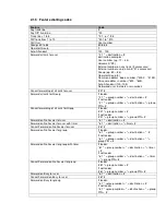
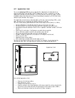
Battery Back-up port
→
→
→
→
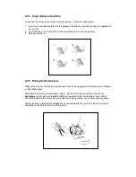
External music-on-hold port
→
→
→
→
External paging port
→
→
→
→
RS232 Port via extended cable
Analogue ports (4 a/b extensions)
Numbered 19-22 by default
Digital ports for the connection of
8 Operafone extensions.
Numbered 11 to 18 by default
→
Ethernet LAN port
RL1
RL2
→
1 RJ-45
→
1 cage clamp
3 RJ-45 connectors, permanently
configured for connection of
3 ISDN lines (T-Interfaces)
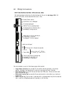
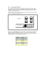
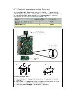
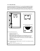
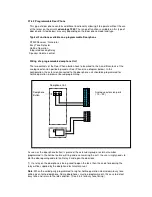
2.2 Wiring Connections
2.2.1 Terminal Connectors in the Access Area
The following diagram illustrates the terminal layout of the
eircom
advantage
1200
. All
terminal connectors are located within the Access Area.
The terminal blocks consist of the following type of connectors:
o
Cage clamp connectors
are used for the connection of back-up battery, relay driven
devices, analogue and Operafone D1 extensions and optional So-Bus Interface.
o
RJ-45 connectors
are used for the connection of the ISDN Lines, So-Bus Interface and
Ethernet LAN/WAN ports.
o
Phono-Jack connectors
are used for the connection of the external Music-on-Hold and
Paging units.
o
RS232 Connector
( 9 pin female ) is provided via an extended cable from the main board
and is used for call logging equipment requiring a serial interface.
For connection of 4
th
ISDN line
(T-Interface) or 1 Internal So-Bus
2 Relay ports for Doorphone operation


