EINHELL 43.406.40 Operating Instructions Manual Download Page 21

Finally, tighten all screws and nuts.

7.2.2 Width extension tables (Abb. 21/22)

Slide the width extension tables by their 
connecting tubes into the prepared mounts as 
far they will go, making sure that the numerical 
scale always faces the front of the machine.

Secure the width extension tables in place with 
the clamping screws (21) underneath.

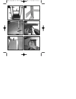
7.3 Fitting / removing the saw blade guard (Fig. 3)

Mount the saw blade guard (2) on the splitter (5) 
so that the screw fits through the hole (44) in the 
splitter.

Do not tighten the screw (15) too far – the blade 
guard must be able to move freely.

Fasten the extractor hose (13) to the extractor 
adapter (16) and to the extractor socket of the 
blade guard (2).

A suitable extractor system has to be connected 
to the outlet of the extractor adapter (16).

To remove the saw blade guard, proceed in 
reverse order.

Important!
The guard hood (2) must always be lowered 
over the workpiece before you begin to cut.

7.4. Setting the splitter (Fig. 3/6/7/8)

Important! Pull out the power plug.

Set the blade (4) to max. cutting depth, move to 
0° position and lock in place.

Remove the saw blade guard (see 7.3).

Take out the table insert (6) (see 7.5).

Slacken the fixing screw (20).

7.4.1. Setting for maximum cuts (Fig. 6/7/8)

Push up the splitter (5) until the gap between the

saw table (1) and the upper edge of the splitter 
(5) equals approx. 10 cm.

The distance between the blade (4) and the 
splitter (5) should be 3-8 mm.

Retighten the screw (20) and mount the table 
insert (6) (Fig. 7).

7.5 Changing the table insert (Figure 7)

To prevent increased likelihood of injury the 
table insert should be changed whenever it is 
worn or damaged.

Remove the saw blade guard (2).

Remove the 2 countersunk head screws (34).

Take out the worn table insert (6).

To fit the replacement table insert, proceed in 
reverse order.

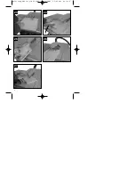
7.6 Fitting/replacing the blade (Fig. 5)

Important! Pull out the power plug first.

Remove the table insert by undoing the two 
countersunk head screws (see 7.5).

Undo the nut  with a size 24 wrench on the nut 
itself and a second fork wrench (size 13) on the 
motor shaft to apply counter-pressure.

Important! 

Turn the nut in the direction of 

rotation of the saw blade.

Take off the outer flange and pull the old saw 
blade off the inner flange by dropping the blade 
at an angle.

Clean the blade flange thoroughly before fitting 
the new blade.

Mount and fasten the new saw blade in reverse 
order.

Important! Note the running direction. The 
cutting angle of the teeth must point in 
running direction, i.e. forwards (see the 
arrow on the blade guard).

Refit and set the splitter (5) and the saw guard 
(2) (see 7.3., 7.4.)

Check to make sure that all safety devices are 
properly mounted and in good working condition 
before you begin working with the saw again.

8.0. Using the saw

8.1. ON/OFF switch (Fig. 4)

To turn the saw on, press the green button .I. . 
Wait for the blade to reach its maximum speed 
of rotation before commencing with the cut. 

To turn the machine off again, press the red 
button “0”.

8.2. Cutting depth (Fig. 4)

Turn the hand crank (8) to set the blade (4) to 
the required cutting depth.

Turn anti-clockwise: 

larger cutting depth

Turn clockwise: 

smaller cutting depth

8.3. Parallel stop

8.3.1. Stop height

The parallel stop (7) supplied with the bench-
type circular saw has two different guide faces.

For thick material you must use the stop rail (25) 
as shown in Fig. 12, for thin material you must 
use the stop rail as shown in Fig.11.

To change over the stop rail (25) to the lower 
guide face you have to slacken the two knurled 
screws (26) in order to disconnect the stop rail 

GB

21

Anleitung TKS 18-250 UV SPK7  13.11.2006  15:25 Uhr  Seite 21

Summary of Contents for 43.406.40

Page 1: ...Art Nr 43 406 40 I Nr 01024 Operating Instructions Bench Type Circular Saw TKS 18 250 UV e eO O d d b b V VB B v vJ J U UH H t tI I d d Anleitung TKS 18 250 UV SPK7 13 11 2006 15 25 Uhr Seite 1...

Page 2: ...Read and follow the operating instructions and safety information before using for the first time bOM t3u UN t d tF UD vML d c UH ULM s U UH q Anleitung TKS 18 250 UV SPK7 13 11 2006 15 25 Uhr Seite...

Page 3: ...3 1 3 35 7 36 13 43 1 36 12 22 10 21 12 15 4 11 9 8 2 2 5 3 16 50 4 Anleitung TKS 18 250 UV SPK7 13 11 2006 15 25 Uhr Seite 3...

Page 4: ...4 5 6 8 7 6 34 23 20 44 Anleitung TKS 18 250 UV SPK7 13 11 2006 15 25 Uhr Seite 4...

Page 5: ...5 9 10 32 49 49 14 39 11 25 45 12 25 Anleitung TKS 18 250 UV SPK7 13 11 2006 15 25 Uhr Seite 5...

Page 6: ...6 16 14 15 13 25 26 24 14 Anleitung TKS 18 250 UV SPK7 13 11 2006 15 25 Uhr Seite 6...

Page 7: ...7 19 20 21 22 17 18 41 40 42 43 35 36 21 Anleitung TKS 18 250 UV SPK7 13 11 2006 15 25 Uhr Seite 7...

Page 8: ...8 25 26 27 23 24 3 Anleitung TKS 18 250 UV SPK7 13 11 2006 15 25 Uhr Seite 8...

Page 9: ...t t3u v u UH t bM U O eO U UH d U u u d U U U t d b b bO ULM t U t vzUM U b U bM U O bN dOLF u UN u U UH sO4 v UL 4 dD8 u UIO u dO AO dI b U t c bM U b u d U U X bN t u d v uL b u b u U d bM U t d t3u...

Page 10: ...t8U bOA dO d bOM UH t8U t q U UB q u eO U t v d U d q UI U q U b bN jO UH U d d bOM u8 fO8 u d u8d v U vzUM u U q t bOM X b U q U U U U UF U vJ e d U U bOM u8 UF XM U UA UN U bOM UH V UM U U bMM dO d...

Page 11: ...b U b UL v U U rOEM t8U d u U8 u u U q d l u bOAJ e d U U U U bF b U vML v UH4 UN L U9 b u VB b tK U bN X d dOLF bMM bO u bN dOLF U vML d c b U vM UB A g b bO UN UOI sOM L b u U d v uL vML vM b u uLF...

Page 12: ...vML pMO bOM UH vML v u bOM UH v HM p U v v u u v v u u e eO O U tFD d b s U d U U4 s U v u u UA eO LPA q v A q v A v u u U b eO LWA q v A q v A b U u v u v u bO u eO d U UL b U d UI r dOK b u vIK U q...

Page 13: ...KN dN UN O U9 b d d t U UN dL f qJ bOM rJ U e eO O v v u u v v d d t tF F u u q qJ J e eO O v v u u t tF F u u t t H H vFK g UN O pL t eO tF u t H bOM O eO t q X U4 t t u d U dN t H t eO t b t eO b bN...

Page 14: ...D v vM MF F X X d d4 4 d dO O b b U U U U b bO OM M X X t tG GO O v vM ML L U UH H4 4 U u b tGO vML UH4 UJ u g t u tF3 d bOM rOEM d M vML UNA dJKL b U b UH q b u d d U U q qJ J q q l lD D b bO OK K e...

Page 15: ...AO v u d p U tFD u s b bN U t U tFD t p d s U d d eO D XL b UA u b r8 U tFD tAOL b U vML UH4 dO O U U XOF b U X u O v u d u b U bM U U p d XN3 U tFD UH U o UD u b bN U g t u tF3 d bOM rOEM dE u UMN bO...

Page 16: ...n u b bN U UO u bOM UA u b bN U t rJ U tFD bO bOM s U tFD u b bN U d U d bO X d4 uK3 dD tGO XN3 bOMJO U U t U vA tAOL t3u u d d t U tFD t b bN rJ dO O q U lD U U tAOL u b bN U b d uK3 t U tFD t bOM U...

Page 17: ...area The same applies for the general rules of occupational health and safety The manufacturer shall not be liable for any changes made to the machine nor for any damage resulting from such changes E...

Page 18: ...any unnecessary objects An untidy work area invites accidents Do not allow other persons especially children to touch the tool or cable Keep them out of your work area Persons working on the machine s...

Page 19: ...heavy duty work Do not mis use the cable Make sure you stand squarely and keep your balance at all times Check the tool for damage Each time before re using the tool carefully check that the guards o...

Page 20: ...bench or it must be bolted to a strong base All covers and safety devices have to be properly fitted before the machine is switched on It must be possible for the saw blade to run freely When working...

Page 21: ...he worn table insert 6 To fit the replacement table insert proceed in reverse order 7 6 Fitting replacing the blade Fig 5 Important Pull out the power plug first Remove the table insert by undoing the...

Page 22: ...the fixing handle 9 Turn the handle to set the desired angle on the scale Lock the fixing handle again in the required angle position 9 0 Operation Important After every new adjustment we recommend y...

Page 23: ...ecessary use the stop rail 25 Press the workpiece firmly against the cross stop 14 Switch on the saw Push the cross stop 14 and the workpiece toward the blade in order to make the cut Important Always...

Page 24: ...e a a daki uygunluk a kla mas n sunar z C dichiara la seguente conformit secondo la direttiva UE e le norme per l articolo l attesterer f lgende overensstemmelse i henhold til EU direktiv og standarde...

Page 25: ...Infoserver http www isc gmbh info 25 WARRANTY CERTIFICATE The product described in these instructions comes with a 2 year warranty covering defects This 2 year warranty period begins with the passing...

Page 26: ...ementation in national laws old electric tools have to be separated from other waste and disposed of in an environment friendly fashion e g by taking to a recycling depot Recycling alternative to the...

Page 27: ...27 Technical changes subject to change X uH vM dOOG t u d o4 Anleitung TKS 18 250 UV SPK7 13 11 2006 15 25 Uhr Seite 27...

Page 28: ...or in part of documentation and papers accompanying products is permitted only with the express consent of ISC GmbH U t d UM vA U U9 dO J t u d U U b b X d d u t uM U s ULM ISC GmbH b U O EH 11 2006...

Reviews: