


C
TROUBLESHOOTING
EG4xxx Owner’s Manual
C.1
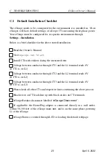
Default Installation Checklist
The eGauge needs to be configured for the environment it is installed in. Most
eGauges will have default settings of all rope CTs measuring three-phase power.
Your eGauge must be configured for its specific environment through
Settings
→
Installation
.
Below is a brief checklist for the above stated installation.
Read the Owner’s Manual.
Visit
egauge.net/start
Install CTs with stickers facing the measured item.
Voltage between conductor through CT1 and the L1 terminal reads 0V
(If CT1 is on L1).
Voltage between conductor through CT2 and the L2 terminal reads 0V
(If CT2 is on L2).
Voltage between conductor through CT3 and the L1 terminal reads 0V
(If CT3 is on L3)
Phase check all other CTs and respective lines continuing the above process.
Black wires on CT leads line up with black circles on CT terminals.
eGauge Breaker disconnect labelled “
eGauge Disconnect
”.
If applicable, the HomePlug adapter is connected directly in a wall outlet,
within 50-100 feet of the eGauge main unit, and is on the same phase powering
L1 of the eGauge.
eGauge Status is verified through LCD or loading the default webpage.
23
April 6, 2022


