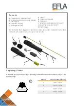
EFLA KDR600 Series Manual Download Page 2

A

.  Plug elastomer housing (male) 

B

.  Receptacle elastomer housing (female) 

C

.  End cap (x2)

D.  

Protective cap (x2)

E.  

Locking device (x2)

Contents 

F.   

Socket

G.   

Guiding pin (plastic)

H.   

Metal pin   

I.   

Screen conducting wire and ring (x2)

J. 

Screw type connector (6mm²) 

K. 

Plastic gauge


Not illustrated: Resin Bag (resin + hardener), Gloves, Sandpaper,  Installation instructions, 

2 strips of self‐vulcanizing tape, measure to strip cable
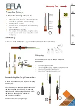
Preparing Cables

1. Trim the end cap component (C) according to ABCD dimension table below and pass the 

cable through.

Material

KDR600 End Plug

Description3

1

2

3

4

5

6

7

8

1

8

7

6

5

4

3

2

A

B

C

E

D

F

F

E

D

C

B

A

OS433

Injection Mold Part

Descriptions

Rev

100256

Drawing number

2:1

Size / Scale

Tolerance:

Mass

2.5 g

Approved by

Designed By

A3

Rev Description

Designed By

Approved by

Date

Date

Surface Treatment

Material <not specified>

ECO Number

Options

  Cable diameter (Ø mm)

A

9,00 – 10,50

B

10,30 – 13,00 

C

13,00 – 15,50

D

15,50 – 19,00

1

G

K

C

A

D

B

H

F

E

I

J

Summary of Contents for KDR600 Series

Page 1: ... installation instructions In case the resins last date of use is expired or the resin containing aluminum bag is damaged Do not use the resin Note Installation temperature range is 50C to 450C Stocking temperature range is 100C to 400C Check www efla net for possible updates of installation instructions Dimensional Data EFLA Type Conductor size mm2 AWG Cable diameter mm inch Diameter Length of as...

Page 2: ... type connector 6mm K Plastic gauge Not illustrated Resin Bag resin hardener Gloves Sandpaper Installation instructions 2 strips of self vulcanizing tape measure to strip cable Preparing Cables 1 Trim the end cap component C according to ABCD dimension table below and pass the cable through 3 4 5 6 7 8 D C B A Options Cable diameter Ø mm A 9 00 10 50 B 10 30 13 00 C 13 00 15 50 D 15 50 19 00 1 G K...

Page 3: ...ea Screening 3 Place a screen continuity s ring around the cable shield area and crimp it 3 90 Crimp Crimp Crimping 3 Crimp the metal pins H F to the cable conductors Crimp at two positions Turn the cable min 90o between the two crimps Size 6mm AWG 8 for KDR600 Size 10mm AWG 6 for KDR600 2 Assembling the Plug Connectors 4 Place the measuring tool K onto the plug housing A 5 Position screen continu...

Page 4: ...uity wire in line with the receptacle housing B and push the pin and cable through the connector Verify the nominal dimension 27 mm using the measuring tool K 10 Remove the measuring tool K and guiding pin G Resin Filling 11 Place the connector housings separately on a horizontally flat surface Make sure that both housings are clean and dry 12 Mix the resin according to the instruction on the resi...

Reviews: