8
ASSEMBLY INSTRUCTIONS
PREPARATION
A. Make sure that you have adequate work space around the item.
B. Use the hardware package provided when assembling unit.
C. Confirm all necessary parts and tools are available (Note: Instruction sheet above will have an exploded
drawing with all single parts marked with numbers).
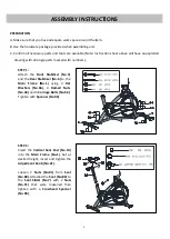
STEP 1:
Attach the
Front Stabilizer (No.5)
and the
Rear Stabilizer (No.6)
to the
Main Frame (No.1)
using 4
Flat
Washers (No.66)
, 4
Domed Nuts
(No.44)
and 4
Carriage Bolts (No.56)
.
Tighten with
Spanner (No.92)
.
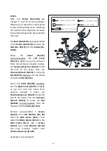
STEP 2:
Insert the
Vertical Seat Post (No.10)
into the
Main Frame (No.1)
. Set at
desired height, insert and tighten the
Adjustment Knob (No.21).
Loosen 2
Nuts (No.91)
from
Seat
(No.80)
. Attached the
Seat (No.80)
to
the
Seat Slider (No.7)
with 2
Nuts
(No.91)
that were loosened then
tighten with a
Crosshead Spanner
(No.94)
.
Summary of Contents for IC037
Page 2: ......
Page 4: ...3 EXPLODED DRAWING 1...
Page 5: ...4 EXPLODED DRAWING 2...
Page 8: ...7 HARDWARE PACKAGE...
Page 19: ...18...
Page 20: ...19...


