background image


STEP 4:


Note:

 The 

Pedals (No. 27L/R) 

are marked 

"L" and "R" for Left and Right. Make sure 
you  attach  the  correct  pedal  to  the 
corresponding crank. Attaching the pedal 
to the wrong crank can cause irreversible 
damage to both the pedal and the crank. 
The 

Bolts  (No.  91L/R)

  are  preassembled 

to 

Pedals (No. 27L/R)

.


Attach 

Left Pedal (No. 27L) 

to 

Left Crank 

(No.  29

).  Turn  the 

Left  Pedal  (No.  27L)


counter-clockwise

  with  hand  until  it  is 

tight,  then  use 

Crosshead  Spanner  (No. 

89)

  to  securely  tighten.  Use

  Crosshead 

Spanner (No. 89) 

to hold the bolt of the 

pedal  in  place,  then  use 

Open  Wrench 

(No.  92)

  to  screw  the 

Nut  (No.  91L)


tightly  in  a 

clockwise

  direction  to  the 

thread end of the 

Left Pedal (No. 27L)

Attach 

Right  Pedal  (No.  27R)

  to 

Right 

Crank (No. 28). 

Turn the 

Right Pedal (No. 

27R)


clockwise 

with hand until it is tight, 

then  use 

Crosshead  Spanner  (No.  89)

 to 

securely tighten. Use 

Crosshead Spanner 

(No. 89)

 to hold the bolt of the pedal in 

place, then use 

Open Wrench (No. 92)

 to 

screw  the 

Nut  (No.  91R) 

tightly


in  a 

counter-clockwise

 direction to the thread 

end of the 

Right Pedal (No. 27R)

 
Remove  2  pre-assembled 

Screws  (No. 

42) 

and 2

 Flat Washers (No. 43)

 from the 

Main  Frame  (No.  1)

.


Then  attach 

the 

Bottle Holder (No. 66)

 to the 

Main Frame 

(No. 1)

 with 2 

Screws (No. 42)

 and 2 

Flat 

Washers (No. 43) 

that were removed. Use 

Crosshead Spanner (No. 89)

 to tighten.


Assembly is now complete! 


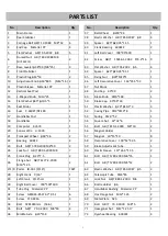
Summary of Contents for IC033

Page 1: ...NDOOR BIKE MODEL NO IC033 IMPORTANT Read all instructions carefully before using this product Save this manual for future reference EXERCISE EQUIPMENT QUESTIONS Contact customer service at service zoo...

Page 2: ......

Page 3: ...ult use only Keep children and pets away from the machine DO NOT leave children unattended in the same room with the equipment 4 Use the equipment on a solid flat level surface with a protective cover...

Page 4: ...3 EXPLODED DRAWING...

Page 5: ...1 17 Handlebar Post 1 53 Spring 2 0 52 1 18 Handlebar 1 54 Square Nut 32 32 6 1 19 Computer X 3574 1 55 Bolt GB T 819 1 2000 M5 10 2 20 Sensor Wire L 1400 1 56 Magnet Holder 1 21 Transport Wheel 69 2...

Page 6: ...Right Decorative Cover 164 37 5 32 1 86 Adjustment Knob M10 25 1 77 Sensor SR 212 1 87 Hexagonal Nut M8 7 78 Sensor Holder LTF8163 1 88 Inner Hexagon Spanner S 6 1 79 Magnet c 02Z 1 89 Crosshead Span...

Page 7: ...HARDWARE PACKAGE NO 10 1PC NO 89 1PC NO 88 1PC NO 90 1PC NO 92 1PC NO 10 1PC NO 14 1PC NO 13 1PC NO 85 1PC NO 86 1PC Tools Accessories for Bike Tools Accessories for Bike NO 3 4PCS NO 5 4PCS NO 6 4PC...

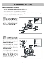
Page 8: ...eat Slider No 15 to the Vertical Seat Post No 12 using the Adjustment Knob No 86 and the Flat Washer No 85 Loosen 2 Hexagonal Nuts No 87 from Seat No 16 Attach the Seat No 16 to Seat Slider No 15 with...

Page 9: ...ob No 10 Attach Handlebar No 18 to Handlebar Post No 17 using L Shaped Knob No 13 and Flat Washer No 14 NOTE Make sure L Shaped Knob No 13 is securely tightened Attach Computer No 19 to Handlebar No 1...

Page 10: ...h No 92 to screw the Nut No 91L tightly in a clockwise direction to the thread end of the Left Pedal No 27L Attach Right Pedal No 27R to Right Crank No 28 Turn the Right Pedal No 27R clockwise with ha...

Page 11: ...the Brake Knob No 49 clockwise To decrease the tension turn the Brake Knob No 49 counter clockwise B Emergency Brake Function The Brake Knob No 49 is also the emergency brake Use this safety feature i...

Page 12: ...ed position Once positioned tighten the Adjustment Knob No 86 to secure the Seat Slider No 15 in place C To adjust the height of Handlebar No 18 loosen and pull on the Adjustment Knob No 10 then slide...

Page 13: ...d No 2 To adjust use the Crosshead Spanner No 89 to loosen the Hexagonal Nut No 87 by turning it clockwise With the Hexagonal Nut No 87 loosened rotate the Base Leveler No 7 until it sits level with t...

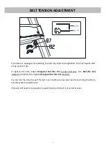
Page 14: ...al Nut No 87 counter clockwise turn Bolt No 82 clockwise to tighten then tighten Hexagonal Nut No 87 clockwise You can turn the crank to see if the belt runs smoothly but we also recommend riding the...

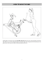
Page 15: ...ach side of the Handlebar No 18 Place one foot on the front base and tilt the bike towards you until the transport wheels on the front base touch the ground With the wheels on the ground you can trans...

Page 16: ...Do not mix old and new batteries Do not mix battery types Dispose old batteries according to your regional guidelines COMPUTER INSTRUCTIONS 1 Press MODE button to select speed distance time and clock...

Page 17: ...l can be pickup is 99 9MPH TRIP DISTANCE 0 00 999 9 MILE CALORIES 1 999 9 CAL ODO 1 999 MILE RPM 0 199 RPM MIN CLOCK 0 00 11 59 and 0 00 23 59 PULSE 40 206 BPM BATTERY TYPE 2pcs of SIZE AAA or UM 4 OP...

Page 18: ...17...

Page 19: ...18...

Page 20: ...19...

Reviews: