background image

36

Service Guide: Fiery Central Solo for KM

Service Procedures

DIMM

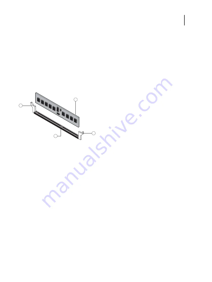
A DIMM (dual in-line memory module) is held in place by levers at the end of the DIMM socket. 

The standard memory configuration is 4GB of memory.

To remove or replace a DIMM

1

Shut down and open the FC Solo (see 

page 22

). 

To remove a DIMM, you must remove the side panel.

2

To release a DIMM, push outward on the levers on each side of the DIMM.

Figure 16:

Removing or replacing a DIMM

3

Lift the DIMM straight out of the socket. 

4

To replace a DIMM, position the DIMM in the socket and press the DIMM straight down into the socket so the 

levers lock the DIMM into place. 

Note: 

DIMM fits in the socket only one way. The notch on the bottom of each DIMM should line up with the notch 

in the socket. 

Make sure that the levers close securely around the ends of the DIMM and the DIMM is fully seated in its socket.

5

Reassemble the FC Solo and verify functionality (see 

page 50

).

6

If you installed a new DIMM, make sure to reset the system date and time (see 

page 30

).

1

Lever

2

Socket notch

3

DIMM

1

2

3

1

Summary of Contents for Fiery Central Solo

Page 1: ...Fiery Central Solo for KM Service Guide A guide for service technicians Replacement parts and specifications are subject to change For a current parts list contact your authorized service support center ...

Page 2: ...is subject to change without notice and does not represent a commitment on the part of EFI The documentation is further covered by Legal Notices distributed with this product The documentation may be provided in conjunction with EFI Software Software and any other EFI product described in the documentation The Software is furnished under license and may only be used or copied in accordance with th...

Page 3: ... Starting shutting down restarting and rebooting 13 Service Procedures 16 Overview 16 FC Solo overview diagrams 17 Accessing internal components 21 Shutting down the system 22 Opening the FC Solo 22 Removing and replacing FC Solo components 25 User Interface Board 26 Motherboard 29 Replacing parts on the motherboard 35 DIMM 36 CPU and CPU cooling assembly 37 Chassis fan 41 Power supply 42 Hard dis...

Page 4: ...icense Manager 53 Configuring FC Solo 54 Fiery Central Configure 55 Troubleshooting 57 Troubleshooting process 57 Preliminary on site checkout 57 Checking external connections 58 Checking internal components 58 Inspecting the system 59 Normal startup sequence 63 Error messages and conditions 63 Specifications 69 Hardware features 69 Physical specifications 69 Safety and emissions compliance 69 Ind...

Page 5: ...attery 30 Figure 13 Cable connections for power button 31 Figure 14 Diagram of the FC Solo motherboard 32 Figure 15 Removing the motherboard from the chassis 34 Figure 16 Removing or replacing a DIMM 36 Figure 17 CPU cooling assembly 37 Figure 18 Removing the CPU cooling assembly 38 Figure 19 Removing replacing the CPU 39 Figure 20 Locating the flat corner of the CPU socket 40 Figure 21 Removing r...

Page 6: ...bout any FC Solo components that do not match the illustrations in this document contact your authorized service support center Terminology and conventions The following sections explain the terminology and conventions used throughout this document FC Solo components The terms replace and replacing are used throughout this document to refer to the reinstallation of existing components Install new ...

Page 7: ...e impresión agarrándolo por el panel superior El panel superior no soporta el peso del sistema Aviso Nunca erga o servidor de impressão pelo painel superior O painel superior não suporta o peso do sistema Waarschuwing Til de afdrukserver nooit op door het bovenpaneel vast te nemen Het bovenpaneel kan het gewicht van het systeem niet dragen Avoid pressing the surface of the LCD Applying excessive p...

Page 8: ...nto a switchable power outlet This can result in the FC Solo being turned off accidentally Do not attempt to open the power supply DVD drive or hard disk drive Handle the FC Solo LCD window with care If the FC Solo LCD window breaks and the liquid crystal inside leaks out avoid contact with it If you come in contact with the liquid crystal wash it off your skin with soap and water immediately Use ...

Page 9: ...n a ground connected antistatic mat Wear an antistatic grounding strap grounded at the same place as the antistatic mat If that is not possible do the following Attach a grounding strap to your wrist Attach the other end to a good ground When you unpack the FC Solo from the carton for the first time touch a metal area of the FC Solo to discharge the static on your body Before you remove any of the...

Page 10: ...ulletins Note The FC Solo Service Guide is not intended for customer use Do not leave the Service Guide at the customer site after servicing the FC Solo CAUTION Avoid touching magnetic tools to storage media such as hard disk drives Contact between magnetic tools and magnetic storage media may result in data corruption ...

Page 11: ...11 Service Guide Fiery Central Solo for KM Introduction ...

Page 12: ...C Solo operation the control panel displays a static logo screen and the buttons are not functional However during installation of FC Solo server software the control panel displays screens that allow you to proceed through the steps of the installation Figure 1 FC Solo control panel 1 Up button 5 Display window 2 Menu button 6 Line selection buttons 3 Down button 7 First 4 Activity light 8 Fourth...

Page 13: ...ach any cables to it To start the FC Solo 1 Make sure that the power cable is attached and that the power switch is in the ON position 2 Press the power button on the front panel Line selection buttons Use the four line selection buttons on the right side of the control panel to select the command displayed on the corresponding line of the LCD display Up and Down buttons Use these buttons to scrol...

Page 14: ...rd During installation a localhost connection to Command WorkStation is created so when you start the FC Solo Command WorkStation starts also To shut down or reboot the FC Solo Note A monitor keyboard and mouse are required to shut down or reboot the FC Solo Use the reset button on the front of the FC Solo only if the system is unresponsive to keyboard or mouse actions 1 On the monitor click the W...

Page 15: ...15 Service Guide Fiery Central Solo for KM Using the FC Solo ...

Page 16: ...terms replace and replacing are used throughout this document to mean the reinstallation of existing components Install new components only when necessary If you determine that a component you have removed is not faulty make sure to reinstall it Replacement parts and specifications are subject to change When ordering replacement parts refer to the current parts list maintained by your authorized s...

Page 17: ...olo components Figure 2 Front and connector panels Front panel Connector panel 1 control panel 6 DVI port covered 2 DVD drive 7 Monitor port option 3 USB port 8 Type A USB port x2 USB 2 0 and network port 4 Reset button 9 Type A USB port x2 USB 3 0 and network port 5 Power button 10 Power connector 11 Power switch 1 2 3 4 5 7 8 9 11 6 10 ...

Page 18: ...olo for KM Service Procedures Figure 3 Internal side view 1 Power supply 5 DVD drive 2 DIMM slots 6 Hard disk drive 3 CPU cooling assembly 7 Motherboard 4 Chassis fan Note Cables UIB or front panel USB port are not shown 1 2 3 4 5 6 7 ...

Page 19: ...e bracket 8 Battery 14 UIB 3 Hard disk drive 9 Motherboard 15 UIB buttons 20 UIB cable 4 Side panel 10 Power supply 16 Hard disk drive SATA cable 21 Front panel USB port and cable 5 DIMM 11 Chassis fan 17 DVD drive bracket 6 CPU cooling assembly 12 Chassis 18 DVD drive Note Tie wraps cable clamps dongle s or external cables are not shown 1 2 3 4 5 6 7 8 9 10 11 12 13 14 15 16 17 18 19 20 21 ...

Page 20: ... From To 1 Front panel USB port cable Front panel USB port Motherboard USB_A2 connector 2 UIB cable User Interface Board Motherboard USB_A1 connector 3 DVD drive power data combo cable DVD drive Motherboard SATA_6G_0 connector 4 Hard disk drive data cable Hard disk drive Motherboard SATA_6G_1 connector 3 2 1 4 1 2 3 4 ...

Page 21: ...erboard power connector 24 pin ATX24P_1 c DVD drive power data combo cable d Hard disk drive power connector 2 Reset cable Reset button front panel Motherboard connector J15 pins 5 and 7 align triangle on cable connector as shown 3 Power cable Power button front panel Motherboard connector J15 pins 6 and 8 align triangle on cable connector as shown 4 CPU fan cable CPU fan Motherboard connector CPU...

Page 22: ...stem has just finished processing wait at least 10 seconds after the system reaches Idle before beginning the shutdown procedure Note Notify the network administrator before you remove the FC Solo from the network 2 On the monitor click the Windows Start button and then click Shut down Before accessing internal components make sure that all cables are disconnected from the back of the FC Solo Open...

Page 23: ...the chassis Set aside the screws so that you can replace them later 3 Slide the side panel toward the connector panel It may help to use the palm of your hand to press down on the side panel as you slide it 4 Lift the side panel off the chassis Figure 7 Removing replacing the side panel Note Before you replace the side panel make sure the top and front panels are installed 5 To replace the side pa...

Page 24: ...he slots in the chassis and then lift the top panel away from the chassis It may help to partially loosen the tabs one at a time as you disengage them from the chassis Figure 8 Removing replacing the top panel 3 To replace the top panel align the tabs on the underside of the panel with the slots on the top of the chassis 4 Press the top panel against the chassis and snap it into place Snap the tab...

Page 25: ...rom the chassis Figure 9 Removing replacing the front panel 3 To replace the front panel align the openings in the panel with the DVD drive power and reset buttons and USB port 4 Press the panel against the chassis and snap it into place Snap the tabs into place one at a time until all four tabs have engaged the chassis Removing and replacing FC Solo components Before replacing costly components b...

Page 26: ... User Interface Board The User Interface Board UIB provides the interface between the FC Solo and the user The front of the UIB contains circuitry for the following Activity lights amber green and red LEDs Display window LCD Four line selection buttons Up and Down buttons Menu button Jewel lights WARNING Be sure to use an ESD grounding wrist strap and follow standard ESD electrostatic discharge pr...

Page 27: ...e User Interface Board 1 Shut down and open the FC Solo see pages 22 and 22 To access the User Interface Board you must remove the side top and front panels 2 Detach the UIB cable from the connector on the top of the UIB Detach the UIB cable by grasping the cable connector Avoid pulling on the cable Front Back 1 Up button pad 7 UIB cable connector 2 Menu button pad 3 Down button pad 4 Display wind...

Page 28: ...the UIB to the mount on the top panel Replace the four screws that secure the UIB to the mount on the top panel Be sure to use the same screws that you removed earlier 8 If you are replacing the UIB cable with a new cable attach the new UIB cable to the connector on the top of the UIB and then route the cable through the hole in the top of chassis and connect it to a USB port on the motherboard 9 ...

Page 29: ...r Débarrassez vous des piles usées conformément aux instructions du constructeur ADVARSEL Lithiumbatteri Eksplosionsfare ved fejlagtig håndtering Udskiftning må kun ske med bat teri af samme fabrikat og type Levér det brugte batteri tilbage til leverandøren VAROITUS Paristo voi räjähtää los se on virheellisesti asennettu Vaihda paristo ainoastaan laitevalmistajan suosittelemaan tyyppiin Hävitä Käy...

Page 30: ...a client computer that is connected to the same network as the FC Solo open a Web browser window 2 In the URL field of the browser type the IP address or DNS name of the FC Solo and press Enter The IP address is listed under the Network Setup section of the FC Solo Configuration page 3 On the WebTools home page click the Configure tab 4 Click Launch Configure type the Administrator password for th...

Page 31: ...on J15 pins 5 green cable and 7 white cable Figure 13 Cable connections for power button CAUTION The following table describes the jumper pin locations on the motherboard Do not move or change any of the default jumper configurations Jumper Description J4 default J4 is the Clear CMOS and Password jumper Default configuration jumper cap installed on pins 2 and 3 Note Because the jumper cap is very ...

Page 32: ...l USB 2 0 port USB_A2 3 USB 2 0 ports 9 CPU and cooling assembly 15 UIB cable USB_A1 4 RJ 45 Network port USB 2 0 ports 10 DIMM slot 16 DVD drive connector SATA_6G_0 5 RJ 45 Network port USB 3 0 ports 11 Reset and Power button cable J15 17 HDD connector SATA_6G_1 6 Chassis fan J21 12 Clear CMOS Jumper J4 MS Mounting screws Note Any connectors not listed are not used 1 2 8 10 MS MS MS MS MS 3 4 5 6...

Page 33: ...2 To remove the motherboard 1 Remove the power supply see page 43 2 Remove the five mounting screws that secure the motherboard to the base of the chassis see Figure 14 on page 32 for the screw locations on your motherboard To minimize tension on the motherboard loosen all the screws partially before removing any one screw completely 3 Remove the two screws from the coverplate on the unused DVI po...

Page 34: ...eplacing the motherboard Use the following procedure to install the motherboard in the FC Solo chassis To replace the motherboard 1 If you are installing a new motherboard do the following Install the DIMM s from the old motherboard onto the new motherboard see page 36 Install the CPU from the old motherboard onto the new motherboard see page 37 When installing these components make sure that the ...

Page 35: ...e remaining motherboard components to complete the motherboard installation To replace motherboard components 1 Replace the following cables to the motherboard for the location of each connector on the motherboard see Figure 5 on page 20 and Figure 6 on page 21 Reset button cable Power button cable 24 pin power cable The cable connector is keyed to fit only one way 4 pin power cable The cable conn...

Page 36: ...or replacing a DIMM 3 Lift the DIMM straight out of the socket 4 To replace a DIMM position the DIMM in the socket and press the DIMM straight down into the socket so the levers lock the DIMM into place Note DIMM fits in the socket only one way The notch on the bottom of each DIMM should line up with the notch in the socket Make sure that the levers close securely around the ends of the DIMM and t...

Page 37: ...ocket remove the motherboard from the chassis see page 33 disconnect the CPU fan cable from the motherboard and remove the cooling assembly from the CPU socket see page 38 The CPU cooling assembly consists of a fan and a heatsink Note Do not remove the CPU fan from the heatsink Figure 17 CPU cooling assembly 1 CPU fan 4 Socket lever 2 Heatsink 5 CPU socket on motherboard 3 CPU 6 Load plate 1 2 3 4...

Page 38: ...before loosening any one screw all the way Lift the cooling assembly off the CPU socket and set it aside Figure 18 Removing the CPU cooling assembly 7 Lift the cooling assembly off the CPU socket and set it aside 8 Unlock the CPU socket lever and raise it into the open position flex the lever away from the retention post and then raise it WARNING Be aware that both the cooling assembly and the CPU...

Page 39: ...ue A thermal pad is preinstalled on the underside of the new CPU cooling assembly If you are installing the existing CPU and CPU cooling assembly on a new motherboard clean the contact surfaces of the CPU and cooling assembly as described above Then apply fresh thermal compound to the contact surface of the CPU using the applicator provided with the new motherboard 2 Prepare the CPU socket by ensu...

Page 40: ...ork surface Apply the fresh thermal compound square as described in step 1 on page 39 Align the cooling assembly so that when it is installed the fan cable easily reaches the CPU fan power connector CPUFAN on the motherboard 7 Place the heatsink over the CPU socket Make sure that the thermal pad on the underside of the heatsink is positioned on top of the CPU Align the four screws with the four sc...

Page 41: ... when the system is on You should hear the chassis fan start as soon as you power on the FC Solo If you do not hear the chassis fan there may be a faulty power connection see Figure 6 on page 21 The following procedures describe how to remove and replace the chassis fan To remove and replace the chassis fan 1 Shut down and open the FC Solo see page 22 To access the chassis fan you must remove the ...

Page 42: ... see Figure 21 5 Verify FC Solo functionality see page 50 Power supply This section describes how to remove and replace the FC Solo power supply For more information on the power supply see Specifications on page 69 You can check power supply functionality using a multimeter at the power cable connectors supplying power to the motherboard CPU HDD and DVD drive Test voltages on the connectors of th...

Page 43: ... the power supply cable from the DVD drive power and data combination cable 5 Remove the 24 pin motherboard power cable from the motherboard 6 Remove the 4 pin CPU power cable from the motherboard 7 Remove the power supply cables secured by the cable harness in the chassis 8 Remove the five screws that attach the power supply to the chassis see Figure 22 on page 44 Set the screws aside so that you...

Page 44: ... power supply make sure to use the screws that came with it to attach the new power supply to the chassis 4 Connect the 4 pin CPU power cable to motherboard connector for connector locations see Figure 14 on page 32 5 Connect the 24 pin motherboard power cable to motherboard connector PW 1 6 Connect a white 4 pin power supply cable to the DVD drive power and data combination cable 1 Power supply c...

Page 45: ... disk drives are hard disk drives shipped without system software installed Proper handling Improper handling can damage a hard disk drive Handle hard disk drives with extreme care Use proper ESD practices when grounding yourself and the FC Solo Keep magnets and magnetic sensitive objects away from the hard disk drive Do not remove the screws on top of the hard disk drive Loosening these screws vo...

Page 46: ... disk drive you must remove the side and front panels 2 Remove the DVD drive see page 48 3 Remove the power supply cable from the hard disk drive 4 Remove the hard disk drive data cable from the hard disk drive 5 Remove the four screws securing the hard disk drive bracket to the chassis 6 Lift the hard disk drive bracket out of the chassis see Figure 23 Figure 23 Removing replacing the hard disk d...

Page 47: ...u install the drive you must install the appropriate system software To replace the hard disk drive 1 If you are installing a new hard disk drive unpack the drive Do not drop jar or bump the hard disk drive Do not touch the hard disk drive with magnetic objects or place objects sensitive to magnets near the hard disk drive 2 Position the hard disk drive inside the hard disk drive bracket and align...

Page 48: ...em date and time see page 30 11 Verify functionality see page 50 DVD drive The DVD drive is attached to a bracket mounted to the hard disk drive bracket and the chassis The DVD drive is used to install system software onto the hard disk drive and archive data onto writable media To remove the DVD drive 1 Shut down and open the FC Solo see page 22 To remove the DVD drive you must remove the side an...

Page 49: ...o the bracket Set aside the screws so that you can replace them later 7 Lift the DVD drive out of the bracket Figure 26 Removing replacing the DVD drive To replace the DVD drive 1 Position the DVD drive inside the bracket and align the mounting holes on the DVD drive with the four holes in the bracket see Figure 25 on page 49 1 Screw 1 of 3 2 DVD drive attached to the bracket 1 DVD drive 2 Screw 1...

Page 50: ...the FC Solo and verify functionality 1 Reseat all boards cables connectors and other parts loosened or removed during service When routing cables inside the FC Solo make sure that Cables are securely installed after routing cables Cable routing does not interfere with the operation of internal components nor interfere with removing or replacing components Cables are not tangled nor looped around i...

Page 51: ... FC Solo software contact your support representative To install the FC Solo software 1 Before you install the server software do the following Connect a monitor mouse and keyboard to the FC Solo Connect the FC Solo to a power outlet Make sure the FC Solo is shut down 2 On the front panel of the FC Solo press the power button Insert the Fiery Central System Software DVD into the DVD drive The FC S...

Page 52: ...d press Enter The default password is Fiery 1 The password is case sensitive 10 When a message is shown asking to install the hardware security key insert the hardware security key to one of the USB port on the FC Solo and click OK 11 At the License Manager window enter the activation key Refer to Installing the hardware security key and Configuring FC Solo for more information Installing the hard...

Page 53: ...new features you must update your license information in the License Manager You can also update your license after the dongle is attached during Fiery Central software installation The License Manager window displays the following information System Serial Number at the top of the license screen indicates the number of your hardware security key Expiration Date at the bottom of the license screen...

Page 54: ...der to start the License Manager 3 Type the activation key code exactly as provided on the Fiery Central Server License Form included in your FC Solo software package and click OK When you type the correct activation key the installer confirms with the message License Installed and updates the current license information 4 Click OK to close the License Manager Configuring FC Solo Some options in S...

Page 55: ...ntral software and restart the server the Fiery Central tray icon appears on the taskbar at the lower right corner of the screen To Configure the Fiery Central server 1 Right click the Fiery Central tray icon select WebTools and then select the Configure tab For information about using Configure and setting default options click Help in WebTools Configure Or in Command WorkStation select Device Ce...

Page 56: ...56 Service Guide Fiery Central Solo for KM Installing FC Solo Software ...

Page 57: ...ent parts list maintained by your authorized service support center Install the correct parts as directed by your service support center Preliminary on site checkout Most problems with the FC Solo are caused by loose board or cable connections This section describes the quick checks you can do to locate and fix obvious problems It describes how to eliminate any problems with external connections t...

Page 58: ...of the FC Solo to check internal components eliminate the most obvious sources of problems Make sure that All interface cables to the system are plugged into the proper connectors see Figure 2 on page 17 The power cable is plugged into the wall power outlet The LED on the network port is blinking to indicate network activity If all the connectors are properly in place and the power is on proceed t...

Page 59: ... the pins are offset from each other the affected board will not function properly 3 Reassemble the FC Solo and verify its functionality see page 50 Inspecting the system If the system you are servicing does not meet a condition listed in Table 2 and it is not obvious what action s you should take to fix the problem for example if the system hangs before reaching Idle locate the symptom in Table 4...

Page 60: ...e drive DVD LED blinks briefly After the system reaches Idle the control panel buttons function Control panel page 12 All replaceable parts are Present Properly aligned Installed securely Installed on the appropriate site The correct part for the system Properly configured if configurable such as hard disk drive jumper Appear undamaged Chassis and contents have not been tampered with Chassis does ...

Page 61: ...ge 26 CPU is Present Well seated Appears undamaged The CPU cooling assembly is Well aligned Firmly attached CPU with cooling assembly page 37 Fan is Properly positioned not backwards Installed in the correct connector Fan fan cable cable connector and mating connector appear undamaged Chassis fan page 41 The power supply required is Present Correctly installed Appears undamaged Cable connectors ar...

Page 62: ...ower supply wire Appears undamaged DVD drive page 48 Each cable required is Present The correct type Installed in the correct connector Well seated Appears undamaged including connectors UIB cable page 20 Hard disk drive data cable page 20 DVD drive power and data combination cable page 20 Power cable s page 21 If included in the system the required mouse monitor and keyboard are present and appea...

Page 63: ...the FC Solo Process Control panel Monitor FC Solo is powered on No backlight Black screen Code in the motherboard BIOS tests initializes and configures areas on the motherboard Lights and then displays efi fiery logo BIOS screen Black screen Windows operating system starts up static logo Windows logo screen Windows Log On Windows desktop appears after you log on with the Admin password Server soft...

Page 64: ...sing a different power cable Install a new or known good power supply 4 Check the chassis and feel for air coming out of the back of the system If air is coming out of the power supply fan vent but is not coming out of the connector panel fan vent the motherboard may be faulty You may need to replace the motherboard see page 29 5 Review the jumper section on page 31 and ensure that the jumper is i...

Page 65: ...een and Activity light appear as follows Possibly one of the following Faulty or incorrectly connected hard disk drive data cable Hard disk drive power cable disconnected Faulty hard disk drive Faulty motherboard 1 Recheck all cables and connections Make sure that the hard disk drive data cable is connected to SATA 1 on the motherboard see Figure 5 on page 20 2 Reboot the FC Solo 3 If the problem ...

Page 66: ... connected System software may be corrupted 1 If the slow start up happens following installation of a software patch or update shut down and then restart to see if the problem persists 2 If the problem persists make sure that the hard disk drive is present and properly connected When you reboot the FC Solo the hard disk drive will be moved to the top of the boot order in the BIOS 3 If the problem...

Page 67: ...ime and date were not configured in Setup afterward the FC Solo will hang during system software installation One of the System Software DVDs is corrupted The DVD drive is faulty The hard disk drive is faulty 1 Set the time and date in the BIOS Power off the FC Solo and remove any media from the DVD drive If not already connected connect a keyboard and a monitor to the FC Solo Power on the FC Solo...

Page 68: ...em software see page 51 Corrupt system software may cause the system to hang 6 If the rest of the network is functioning properly and the problem persists replace the motherboard see page 34 System starts up slowly then displays one or more DHCP error messages on the control panel Possibly one of the following Network cable is connected to the wrong RJ 45 port No cable wrong type of cable is conne...

Page 69: ...onnectivity over twisted pair cable upper port 500GB hard disk drive standard Built in DVD RW drive Physical specifications Operating environment Temperature 5 C to 40 C Relative Humidity 10 85 non condensing Power supply voltage input 100 240V 50 60Hz Power supply current input 100V 2A Max 240V 4A Max Dimensions height x depth x width 32 0 cm 12 5 in x 34 5 cm 15 5 in x 14 0 cm 5 5 in Weight 6 8 ...

Page 70: ...0 1 2006 A11 2009 A1 2010 A12 2011 A2 2013 EMI EMC approvals FCC Title 47 Part 15 Subpart B Class B ICES 003 Issue 5 August 2012 Class B EN55022 2010 EU Class B C TICK mark Australia and New Zealand Class B EN610003 2 2006 Plus A1 2009 A2 2009 EU EN610003 3 2008 EU EN55024 2010 EU ...

Page 71: ...r panel 58 connectors chassis fan 32 connector panel 58 CPU fan cable 32 DIMMs 32 DVD drive data cable 32 front panel USB port 32 HDD data cable 32 monitor option 32 motherboard 32 network 32 58 power and reset pins on motherboard 32 power supply cables 32 power AC 58 UIB cable 32 USB ports dongle 58 control panel activity light 65 buttons 13 26 using 12 cooling assembly CPU 38 covers removing 22 ...

Page 72: ... of 33 N network connector 32 normal startup sequence 63 O opening the system 22 P panels removing 22 25 power AC cable 58 AC connector 58 chassis fan 41 CPU fan 38 40 DVD drive 50 HDD 48 power supply cables 42 removing 43 replacing 44 voltages 14 69 R reassembling the system 50 reset and power buttons 14 22 32 S server setup see server setup service calls checklist 50 service procedures overview ...

Reviews: