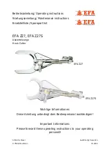
EFA EFA Z27 Operating Instructions, Maintenance Instructions, Spare Part List Download Page 4

Schmid & Wezel
D-75433 Maulbronn

Seite / Page

2/ 12

Ausführung / Execution

05.2004

„

Hydraulic oil

The order numbers for both the parts contained in 

the scope of supply and for accessories can be 

found in Annex A.2 "List of spare and wear parts" 

(pg. 8).

2. Safety Precautions

2.1 General Safety Precautions

Be sure to observe the following safety pre-

cautions when working with the hook cutter.

„

Always disconnect the equipment from the 

power supply before changing the cutting 

blades or starting any installation, maintenance 

and repair work.

„

It is assumed that all work involving operation 

of the hook cutter is always completed by ade-

quately skilled operating personnel.

„

Instruction is provided by our specialist person-

nel. 

„

Installation, maintenance and repair work may 

only be carried out by authorised and qualified 

personnel.

„

Hook cutters from S&W conform to the relevant 

safety regulations. 

2.2 Conduct at the Place of Work

1. Keep your place of work tidy. Untidiness can 

lead to accidents.

2. Give consideration to environmental influences. 

Ensure good lighting (min. 500 lux).

3. Keep other people away from your place of 

work. Work in a concentrated and sensible man-

ner. Do not use the hook cutter when you are 

unconcentrated and/or tired.

4. Keep the hook cutter in a safe place. Store the 

unit in a dry place when not in use.

5. Working clothes: Do not wear any baggy clothes 

or jewellery because these could be caught by 

moving parts. Wear solid shoes when working. 

Wear a hair net as a general rule!

6. Avoid abnormal body postures. Ensure a safe 

working position and keep your balance at all 

times.

7. Service your tools with care. Use only sharp and 

undamaged blades so that you can work better 

and safer.

8. Use only original EFA blades. Follow the instruc-

tions given under "Changing the blades". See 

also Chapter 4.1.1 "Changing the blades" (pg. 4).

9. Do not leave wrenches on the machine. Check 

that all wrenches have been removed before 

starting the equipment.

10.Use only original EFA accessories. Use of other 

accessories will void the warranty. Use of other 

tools or accessories may result in injury to your-

self.

11.Modifications and changes to the machine are 

not permitted and exonerate S&W of any war-

ranty and liability.

3. Commissioning and opera-
tional safety

Place of work
The operator requires a working space of at least 

1.5 sq. m. No other place of work should extend into 

this area, as the movements with the cutter could 

result in the risk of injury.
The illumination at the place of work must be at 

least 500 lux.

3.1 Initial Operation

The hook cutter must be in an 

"off" state when connected to the 

works power network!

Important information, e.g. technical 

data sheets, drawings and parts lists can 

be found in Annex A.2 (pg. 8).

3.1.1 Spring balancer
The machine must always be operated in combina-

tion with a weight relief system (spring balancer). 

Install this above the working area on an element 

assembled higher or on the ceiling. Information on 

fine adjustment of the spring balancer can be found 

in Chapter 4.5 "Adjustment of the Spring Balancer" 

(pg. 4).
Suspend the cutter so that it is as top-heavy as pos-

sible. The vertical position can be adjusted, if nec-

essary.
Due to the weight of approx. 24 kg, there is a risk 

of injury through the unit slipping or falling down 

when fixing or loosening the weight relief system. 

Pay attention also that the machine does not jam 

on the trigger snap or on the hook of the cutter. 

Work cautiously!
When the cutter is not in use, store it so that there 

is no risk of accidental contact with the blades as 

Summary of Contents for EFA Z27

Page 1: ...ingt dem Bedienpersonal aushändigen Important Informations Please forward these operating instructions to your operating personell Betriebsanleitung Operating instructions Wartungsanleitung Maintenance instructions Ersatzteilliste Sparepart list EFA Z27 EFA Z27S Abviertelzange Hook Cutter EFA Z27 EFA Z27S ...

Page 2: ...g with the Hook Cutter 3 4 Assembly 3 4 1 Changing Blades 4 4 2 Valve Replacement 4 4 3 Changing Pistons 4 4 4 Hydraulic Power Unit 4 4 5 Adjustment of the Spring Balancer 4 5 Maintenance 5 6 Cleaning and Maintenance 6 6 1 Daily Cleaning After Completing Work 6 6 2 Daily Maintenance of Cutter 6 6 3 Extended Maintenance after approx 100 operating hours 6 6 4 Repair by After Sales Service 7 7 Transp...

Page 3: ...ase consult Schmid Wezel GmbH Co S W beforehand Use in any other way may result in a risk of acci dents and increased wear The user alone is liable for the consequences of any other form of use 1 2 1 Residual risks Since the cutter is intended for industrial use on an imal carcasses there is a risk of injuring yourself and in the case of extreme misuse of fatally injur ing others Since due to the ...

Page 4: ...u can work better and safer 8 Use only original EFA blades Follow the instruc tions given under Changing the blades See also Chapter 4 1 1 Changing the blades pg 4 9 Do not leave wrenches on the machine Check that all wrenches have been removed before starting the equipment 10 Use only original EFA accessories Use of other accessories will void the warranty Use of other tools or accessories may re...

Page 5: ... 1 Switching on Hold the cutter firmly Actuate the front operating handle simultane ously with the rear operating handle to close the cutter 3 2 2 Switching off Release the operating handles to open the cut ter The cutting process can be interrupted or repeated at any time 3 3 Working with the Hook Cutter Never reach into the cutting area of the cutter to avoid the risk of cutting off limbs Wear e...

Page 6: ... to release the handle 23 Remove the snap ring 22 and pull out the valve 17 21 clean the removed parts inspect them for wear and install again in the reverse order Always replace the valve 17 21 together with the snap ring 22 4 3 Changing Pistons Replacing the piston parts The assembly kit must be available for this repair See also Annex A 2 List of spare and wear parts pg 8 Remove the blades 36 s...

Page 7: ...ck and replace if necessary 6 Coupling connector of the hydraulic return flow hose is not connected properly Connect the hose correctly 7 Gaskets defective Inspect the gaskets and replace if necessary 8 Oil level too low Refill oil see Chapter 3 1 2 Hydraulic power unit pg 3 When actuating the trigger lever the pump starts but the cutter closes slowly 9 Oil filter on the pump clogged Change the oi...

Page 8: ...esses The above cleaning agents are only a recommenda tion if other cleaning agents are used the customer should examine the material compatibility and com pliance with the hygiene regulations 6 1 3 Lubricants and hydraulic oil The lubricant and the hydraulic oil have to meet the regulations for the foodstuffs sector DIN 1672 Recommended lubricating grease Klübersynth UH1 14 22 1 kg special grease...

Page 9: ...epair by After Sales Service Disconnect the machine from the works mains before starting any repair work Repairs may only be carried out by specialist personnel Our Service department is at your disposal for all repair work In the event of a repair please contact your nearest contract workshop or our parent company directly On request spare parts lists can be supplied to the repair workshop with q...

Page 10: ...8 535 008 010 524 Hydraulic cylinder assy 1 13 001 964 050 1 1 Guide complete with 2 4 12 001 964 046 2 1 Stripper 001 964 041 3 1 Grooved ring 001 964 039 4 1 Bushing 001 964 038 7 1 Piston rod 001 964 034 8 1 O ring 17x2 001 312 649 9 1 Piston 001 964 032 10 1 Piston seal 001 964 040 12 1 O ring 46x2 001 312 669 13 1 1 Cylindrical tube with end section Bracket assy 14 22 001 964 045 008 005 279 ...

Page 11: ...55 008 005 277 48 1 Flange 003 005 056 49 1 Pressure spring 003 003 932 50 1 Valve pin 003 005 063 51 1 O ring 001 312 620 52 1 O ring 001 312 627 53 1 Valve insert 003 005 055 54 1 O ring 001 312 636 55 1 Snap ring 001 312 313 56 2 Flat head socket head cap screw 001 326 515 57 4 Male fitting 001 610 601 58 2 Flexible Rilsan hose 001 610 658 59 3 Cable tie 001 371 916 60 1 Coupling socket with 61...

Page 12: ...fitting 001 610 601 82 1 Bracket 003 005 067 83 1 Gasket 003 005 396 84 5 Cable tie 001 371 913 Special Accessories 2 Hydraulic oil 20 l 001 365 614 1 Spring balancer 001 620 025 1 Grease gun 001 365 403 1 Special grease 001 365 621 1 Assembly kit 007 899 668 007 899 668 1 Hook wrench 001 370 205 001 370 205 1 Face pin wrench 001 369 705 001 369 705 1 Rotating pin 001 366 005 001 366 005 1 Assembl...

Page 13: ...Schmid Wezel D 75433 Maulbronn Seite Page 11 12 Ausführung Execution 05 2004 A 4 Exploded diagram Z27 Z27S ...

Page 14: ...Maschine Zangen Typ EFAZ 05 06 07 08 10 12 13 14 27 27S 28 28S 078 079 080 085 090 140 ZR27 Antrieb Hydraulikantrieb AngewandteVorschriften Richtlinien 2006 42 EG AngewandteA Normen DINEN1050 AngewandteB Normen DINEN294 DINEN954 1 DINEN954 2 Entwurf AngewandteC Normen EN12984 AngewandtenationaleNormen Machineidentification Cutter Type EFAZ 05 06 07 08 10 12 13 14 27 27S 28 28S 078 079 080 085 090 ...

Reviews: