
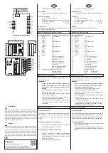

CONNETTORE CABLATO (per la connessione degli ingressi):
1.
NERO
Comune IN/OUT
2.
BIANCO
IN 1
3.
GIALLO
OUT 1
4.
NERO
Comune IN/OUT 2
5.
ROSSO
IN 2
6.
ARANCIO
OUT 2
7.
NERO
Comune IN/OUT 3
8.
VERDE
IN 3
9.
BLU
OUT 3
10.
NERO
Comune IN/OUT 4
11.
VIOLA
IN 4
12.
GRIGIO
OUT 4
13.
-
IN / Sonda temperatura 5
14.
-
IN / Sonda temperatura 6
15.
-
Comune 5-6
16.
-
IN / Sonda temperatura 7
17.
-
IN / Sonda temperatura 8
18.
-
Comune 7-8
19.
-
Tasto di programmazione ETS
20.
-
LED di programmazione ETS
21.
Terminale di connessione bus (a innesto):
-
polo negativo NERO
+
polo positivo ROSSO
WIRED CONNECOTRS:
1.
BLACK
Common IN/OUT 1
2.
WHITE
IN 1
3.
YELLOW
OUT 1
4.
BLACK
Common IN/OUT 2
5.
RED
IN 2
6.
ORANGE
OUT 2
7.
BLACK
Common IN/OUT 3
8.
GREEN
IN 3
9.
BLUE
OUT 3
10.
BLACK
Common IN/OUT 4
11.
VIOLET
IN 4
12.
GREY
OUT 4
13.
-
IN / Temperature sensor 5
14. -
IN / Temperature sensor 6
15. -
Common 5-6
16. -
IN / Temperature sensor 7
17. -
IN / Temperature sensor 8
18. -
Common 7-8
19. -
ETS Programming switch
20. -
ETS Programming LED
21.
-
EIB/KNX Connector
-
BLACK
Bus Negative
+
RED
Bus Positive
General Description
The device configuration (KNX physical address assimnment) is
done by pressing the programming push button. Please take care
during installation to leave connection wires long enough in order
to remove the device easily from the wall box for commissioning.
Connecting bus cables
•
Connect each single KNX/EIB bus core inside the terminal
block observing bus polarity .
•
Slip the bus connection block into the guide slot placed on
the back side of this device and press the block down to the
stop
IMPORTANTE
WARNING
•
Il dispositivo deve essere installato mantenendo una
distanza minima di 4mm tra le linee in tensione non
SELV (230V ) e i cavi collegati agli ingressi o al bus
EIB/KNX.
•
Il dispositivo non deve essere collegato a cavi in tensione
e mai ad una linea a 230 V.
•
L’apparecchio deve essere installato e messo in servizio
da un installatore abilitato.
•
Devono essere osservate le norme in vigore in materia di
si-curezza e prevenzione antinfortunistica.
•
L’apparecchio non deve essere aperto. Eventuali appa
-
recchi difettosi devono essere fatti pervenire alla sede
competente.
L’apparecchio deve essere impiegato per installazione in am-
bienti chiusi e asciutti.
The device may be used for permanent indoor installations in
dry locations within wall box mounts.
Descrizione generale
Per effettuare la messa in servizio occorre poter accedere al ta
-
sto “EIB/KNX” per la commutazione tra modo normale e modo
programmazione che si trova tra i morsetti EIB e i morsetti in
-
gresso.
Collegamento del cavo bus al morsetto bus
•
Il morsetto Bus EIB (compreso nella fornitura) è adatto ad
un conduttore unifilare con Ø 0.8 mm
Collegamento del modulo I/O alla linea bus
•
Inserire il morsetto Bus EIB/KNX, precedentemente
collegato al cavo bus, nel connettore maschio
dell’accoppiatore bus integrato che si trova sul lato
ingressi del dispositivo
•
Inserire il morsetto bus fino all’arresto
•
Device must be installed keeping a minimum distance
of 4mm between electrical power line (mains) and in
-
put cables or red / black bus cable .
•
The device must not be connected to 230V cables.
•
The prevailing safety rules must be heeded.
•
The device must be mounted and commissioned by an
authorised installer.
•
The applicable safety and accident prevention regulations
must be observed.
•
The device must not be opened. Any faulty devices should
be returned to manufacturer.
•
For planning and construction of electric installations, the
relevant guidelines, regulations and standards of the re
-
spective country are to be considered.
Posizione indicatori ed elementi di comando
Avvertenze per l’installazione
Montaggio e collegamento
Indicators and Control Elements
Mounting and wiring hints
Installation Instructions
EN
IT
eelectron spa
Via Monteverdi 6
I-20025 Legnano (MI) - Italia
Tel: +39 0331 500802 Fax: +39 0331 564826
Email: [email protected] Web: www.eelectron.com
SMALTIMENTO
The crossed-out bin symbol on the equipment or packaging means the product
must not be included with other general waste at the end of its working life.
The user must take the worn product to a sorted waste centre, or return it to the
retailer when purchasing a new one. An efficient sorted waste collection for the
environmentally friendly disposal of the used device, or its subsequent recycling,
helps avoid the potential negative effects on the environment and people’s
health, and encourages the re-use and/or recycling of the construction materials.
DISPOSAL
•
Soddisfa EN 50090 e IEC 664-1: 1992
Requisiti EMC
•
Rispettati EN 50081-1, EN 50082-2 e EN 50090-2.2
Condizioni di impiego
•
Secondo norma EN 50090-2.2
•
Temperatura ambiente durante il funzionamento: 0°C + 45°C
•
Temperatura di stoccaggio: - 20 °C + 55 °C
•
Umidità relativa:
max 90 %
Marcatura CE
Conformemente alla direttiva CE (edilizia abitativa e industria
-
le), direttiva sulla bassa tensione.
43
24
NERO / BLACK
BIANCO / WHITE
GIALLO/ YELLOW
ROSSO / RED
ARANCIO/ ORANGE
NERO/ BLACK
VERDE / GREEN
BLU/ BLUE
VIOLA / VIOLET
GRIGIO/ GREY
NERO/ BLACK
NERO / BLACK
1
2
3
4
5
6
7
8
9
10
19
20
13
14
15
16
17
18
21
11
12
BUS KNX
KNX
COM
COM
COM
IN/TS 5
13
1
2
3
4
5
6
7
8
9
10
11
12
14
15
16
17
18
IN/TS 8
IN/TS 7
IN/TS 6
IN
OUT
COM
IN
OUT
COM
IN
OUT
COM
IN
OUT
•
Meets EN 50090 and IEC 664-1: 1992
EMC Requirements
•
Complied with EN 50081-1, EN 50082-2 and EN 50090-2.2
Terms of use
•
According to EN 50090-2.2
•
Ambient temperature during operation: 0 °C + 45 °C
•
Storage temperature:
- 20 °C + 55 °C
•
Relative humidity:
max 90%
CE Mark
According to EMC guideline and low voltage directive
Il simbolo del cassonetto barrato indica che il prodotto alla fine della propria vita
utile deve essere raccolto separatamente dagli altri rifiuti. AI termine dell’utilizzo,
l’utente dovrà farsi carico di conferire il prodotto ad un idoneo centro di raccolta
differenziata oppure di riconsegnarlo al rivenditore all’atto dell’acquisto di
un nuovo prodotto. L’adeguata raccolta differenziata per l’avvio successivo
dell’apparecchiatura dimessa al riciclaggio contribuisce ad evitare possibili
effetti negativi sull’ambiente e sulla salute e favorisce il reimpiego e/o riciclo dei
materiali di cui e composta l’apparecchiatura.


