


2 / 6
P/N 3101077 • REV 05 • REB 23JAN13
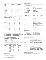
Figure 1: AB4G-SB box installation
1
2
3
4
5
6
7
1.
Conduit connector
2.
AB4G-SB electrical box
3.
Lock tab
4.
Trim rings
5.
Screw
6.
Nut
7.
Reinforcing plate
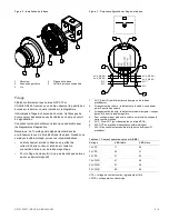
Figure 2: Base installation
1.
Detector
2.
Trim ring
3.
Screw
4.
Base plate
5.
Compatible electrical box
Wiring
Wire in accordance with NFPA 72 and CAN/ULC-S524. Be
sure to observe the polarity of the terminals on the terminal
block as shown in the diagram.
Break the wire run at each terminal. Do not loop signaling
circuit field wires around terminals.
Refer to the applicable technical reference manual for
application diagrams.
Note:
Shielded wire is required only in environments with very
high electrical noise. When you use shielded cable, follow
these recommendations
:
•
Shield connection to and from the base must be
continuous and must be insulated from ground. Insulate
the shield using tape.
•
For Class B wiring, there is no shield connection to ground
at the last device.
Figure 3: Output configuration and wiring diagram
4
SLC
+
SLC
+
AUX_RISER
+
AUX_RISER
+
SLC
−
SLC
−
AUX_RISER
−
AUX_RISER
−
1.
AUX-RISER IN (from power supply or previous base)
2.
Volume setting: default is high volume; cut per item 4 for low
volume
3.
Tone setting: default is temporal pattern; cut per item 4 for steady
tone
4.
To configure output volume or tone, cut the circuit board as
shown
5.
AUX_RISER OUT To next base or EOL relay
6.
SLC OUT to next intelligent addressable device
7.
SLC IN from intelligent addressable controller or previous device


