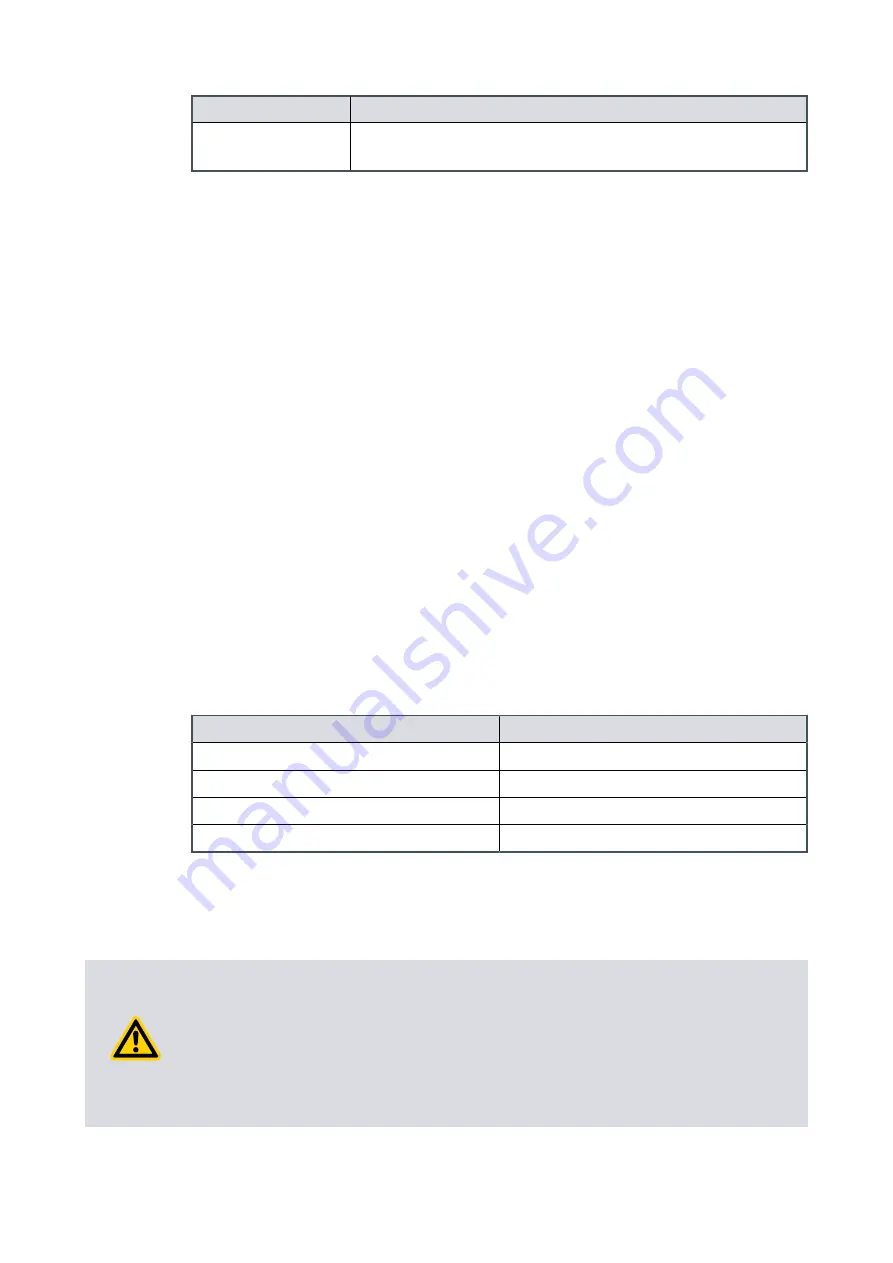
Option number
Description of the vent function
6.7
Vent valve fully opens immediately for the Stop command or
Fail.
When the pump is shipped, the controller is set to the factory default vent option 0,
refer to
Table: Vent options on page 53
. You can configure the controller to one of the
other vent options. Commands can be sent through the serial interface or the
manufacturer's TIC Turbo and Instrument Controller or Turbo Controller.
The controller only operates (shuts) the TAV solenoid valve when it receives a start
command. Before the controller operates (shuts) the TAV solenoid valve, the valve will
be in the 'open' vent state. If the vacuum system is a large system, let backing pump
decrease the pressure in the system to an acceptable level before you start the pump.
Send a command through the serial interface to close the vent valve before you send a
start command. This is known as a delayed start.
If you control the pump with the manufacturer's TIC Turbo and Instrument Controller or
TIC Turbo Controller, the TAV solenoid valve can be operated from the TIC. Refer to the
TIC Instruction Manuals for more information.
4.9.4 Alternative valve connected to the vacuum system
If you use different vent valve, make sure that the applicable vent restrictor is installed in
the vacuum system to limit the rate of increase in pressure. Refer to
restrictor orifice diameter (with atmospheric pressure at the inlet of the vent valve) on
for information about the sizes of vent restrictor. If the applicable vent restrictor
is not installed, open the vent valve only when the speed of the pump decreases to 50%
of the full rotational speed.
Table 17
Vent restrictor orifice diameter (with atmospheric pressure at the inlet of the vent
valve)
Vacuum system volume (litres)
Orifice diameter (mm)
< 20
£
1.0
< 10
£
0.7
< 5
£
0.5
< 2
£
0.35
4.10 Cooling
4.10.1 Introduction
CAUTION: PUMP COOLING
Risk of damage to equipment. Make sure that the pump is sufficiently cooled to
prevent the damage to the rotor and bearing.
When you use an alternative configuration (other than the manufacturer's standard
cooling accessories) to cool the pump, make sure that the cooling is not directed or
ducted onto the pump controller.
Page 54
B85200880_D - Installation


