D397-21-880 Issue G
Page 12
© Edwards Limited 2009. All rights reserved.
Edwards and the Edwards logo are trademarks of Edwards Limited.
Installation
3.3
Controller electrical connections
CAUTION
Do not connect Barocel capacitance manometers to the TIC. Doing so will result in damage to the gauge and will
invalidate the warranty.
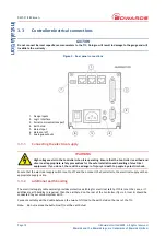
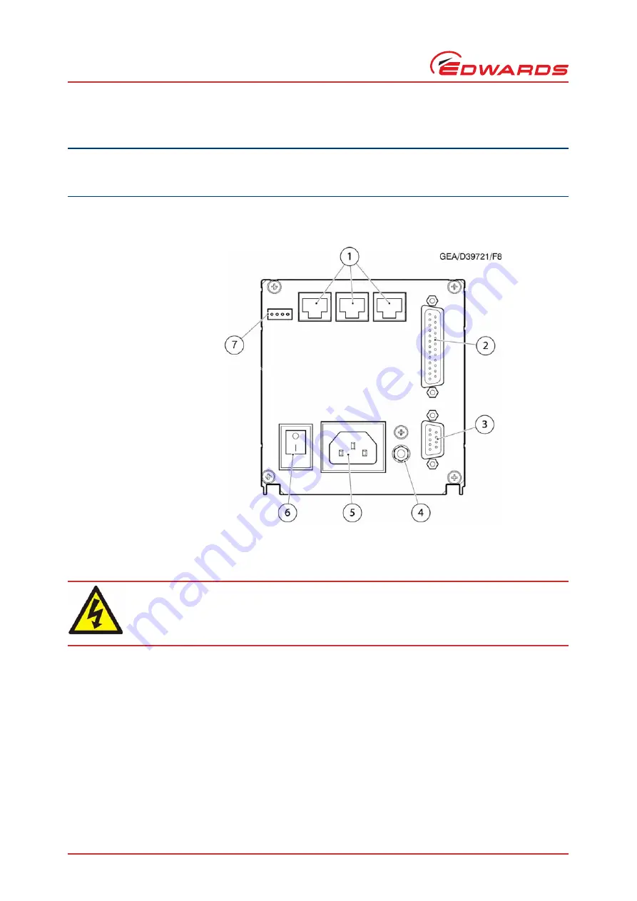
Figure 9 - Rear panel connections
3.3.1
Connecting the electrical supply
Ensure that the electrical supply switch is set to 'off' and then connect the Controller to the electrical supply with an
appropriate supply cable.
3.3.2
Additional earth bonding
The electrical supply cable normally provides protective earthing for electrical safety. If this is not the case, or if
additional earth bonding is required, then the earth stud on the rear of the Controller (
, item 4) should be
connected to your vacuum system earth.
Connect a suitably earthed cable between the two nuts fitted to the earth stud on the rear of the TIC.
Note:
Do not remove the bottom nut from the earth stud.
WARNING
High voltages exist in the Controller when it is operating. Ensure that the Controller is earthed and
observe all appropriate safety precautions for the safe installation and handling of electrical
equipment. If you do not, there will be a danger of injury or death to people by electric shock.
1. Gauge inputs
2. Logic interface
3. Serial communications port
4. Earth stud
5. Mains input
6. Mains on/off
7. Analogue outputs

