4 / 4
P/N 270481 • REV 06 • REB 18JAN13
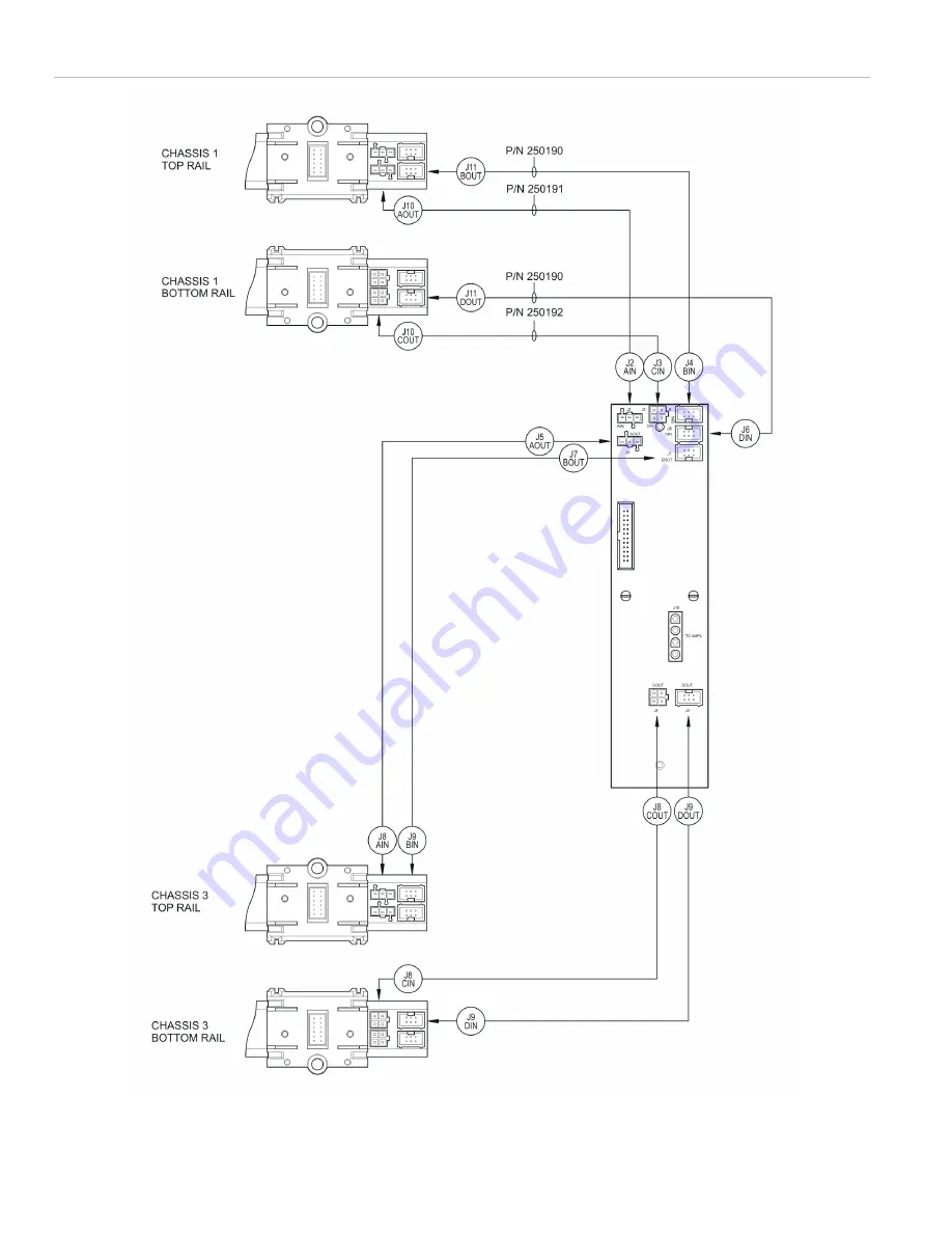
Figure 7: RCIC card wiring diagram
Page 1: ... 2 µF max Operating environment Temperature Humidity 32 to 120 F 0 to 49 C 0 to 93 RH noncondensing at 90 F 32 C Contact information For contact information see www edwardsutcfs com Installation WARNING Remove all sources of power from the cabinet before installing or removing components Failure to do so may result in serious injury or loss of life 1 Attach the chassis to the backbox using the har...
Page 2: ...the ASU card to AUDIO A OUT on the 3 CPUx card See Figure 5 If a 3 RS485 card is installed connect AUDIO DATA PRIMARY on the ASU card to AUDIO A IN on the 3 CPUx card Wiring from a 3 REMICA or 3 REMICP must be shielded and enclosed in conduit See Figure 5 All shields must be continuous and insulated from ground except at the originating panel The REMOTE input is for MNEC applications only Not for ...
Page 3: ...P N 270481 REV 06 REB 18JAN13 3 4 Figure 5 ASU card wiring diagram Figure 6 FTCU card wiring diagram ...
Page 4: ...4 4 P N 270481 REV 06 REB 18JAN13 Figure 7 RCIC card wiring diagram ...