background image

Transmitter - Wireless Pulse Wall Switch 


Ref : IMRF

July 2009 


page 6 


          IMRF

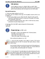
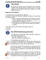
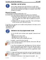
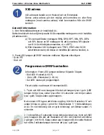
X10 address

The X10 address consists of a HOUSE CODE and UNIT CODE.

This unique address makes it possible to control one or more receivers 

(with the same address) with commands from the IMRF switch.

General Information:

1. The factory default address is set to A1.

This means you can remotely control any X10 compatible receiver which is set 

to address A1:


a) Like e.g. the Ebode receivers RMA, RMV, RPT, RPA, RPL (RPA and RPL 

          require a RF transceiver in order to convert the RF signals to X10 power 

          line commands, e.g the RPT).


b) Or Classic X10 Receivers like the TM13, CM15 or SC28 security console, 

          when set to the same House code, A.

2. The front LED of the IMRF module indicates the following state:

- Green: ON

- Red: OFF

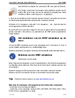
Programming 

the IMRF switch:

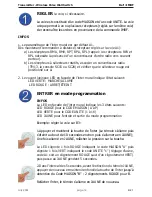
Information: The front LED indicates the 3 following states:

- Red LED: House code (A to P)

- Green LED: Unit code (1 to 16)

- Yellow LED: status of the program mode.

When setting the address to e.g.: B3.

1. Press and hold the button until it lights up yellow. (The led will 

illuminate,  then  off  after  10  seconds,  then  goes  yellow);  release 

button press.

Next the LED will blink once red for the House Code ‘A’ then blink green 

once for the Unit Code ‘1’ (the factory setting is A1: One red blink and 

one green blink), then blinks yellow for 5 seconds.

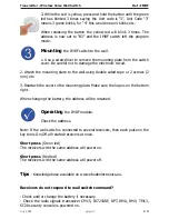
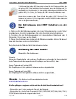
2. In the interval of 5 seconds before the yellow light goes off, press 

and hold the button until the HOUSE code «B»: there will be 2 red 

blinks for B. Release the key at the time the selected Home code is 

reached, the indicator lights up yellow again.

Summary of Contents for XDOM IMRF - PRODUCTSHEET

Page 1: ...er guide 6 Bedienungsanleitung 8 Gebruiksaanwijzing 10 Användermanual 12 Guide utilisateur 14 Guía del usario 16 Manual do utilizador 18 Manuale per l utente 20 IMRF Transmitter Wireless Pulse Wall Switch ...

Page 2: ...nden und Zulassungen verboten Bitte verwenden Sie das Gerät korrekt beachten Sie die Bedienungsanleitung WARNUNG Nicht öffnen Verletzungsgefahr durch elektrischen Schlag In diesem Gerät gibt es lebensgefährliche Stromspannung Enthält keine durch den Benutzer zu wartenden Teile Lassen Sie alle Wartungen von geschulten Kundendiensttechnikern durchführen Wichtig Das Produkt muss gemäß dieser Bedienun...

Page 3: ...rna i de olika kapitlen i användarhandboken För att säkerställa korrekt inställning läs manualen och säkerhets noteringarna noggrant Conseils de sécurité Lisez attentivement ce guide utilisateur afin de garantir une utilisation sûre et sans prob lèmes de ce produit et suivez minutieusement les conseils de sécurité Pour des raisons de sécurité toute manipulation technique ou modification du produit...

Page 4: ...do Importante o producto deve ser usado de acordo com as instruções neste manual e não é conveniente para outros propósitos Evite o seguinte forte desgaste mecânico alta temperatura vibrações fortes humidade alta Por favor também respeita as notas adicionais de segurança nos vários capítulos do guia de utente Para assegurar ajuste correcto por favor lê o manual e notas de segurança cuida dosamente...

Page 5: ...Transmitter Wireless Pulse Wall Switch Ref IMRF July 2009 page 5 IMRF Notes ...

Page 6: ... code A 2 The front LED of the IMRF module indicates the following state Green ON Red OFF Programming the IMRF switch Information The front LED indicates the 3 following states Red LED House code A to P Green LED Unit code 1 to 16 Yellow LED status of the program mode When setting the address to e g B3 1 Press and hold the button until it lights up yellow The led will illuminate then off after 10 ...

Page 7: ...ate to the wall using double sided tape or 2 screws 2 mm etc 3 Reattach the cover to the mounting plate Make sure the logo is on the bottom right When changing the battery the address will be retained Operating the IMRF module Check the address Note If the wall switch is connected to several receivers then each pulse on the key turns On Off all related receivers at once Short press Green led The r...

Page 8: ...vordere LED des IMRF Moduls zeigt folgenden Status an Grün EIN Rot AUS Den IMRF Schalter programmieren Informationen Die vordere LED zeigt die folgenden 3 Zustände an Rote LED Hauscode A bis P Grüne LED Gerätecode 1 bis 16 Gelbe LED Status des Programmiermodus Bei Einstellung der Adresse auf z B B3 1 Halten Sie die Taste gedrückt bis die gelbe LED aufleuchtet Die LED leuchtet auf geht dann nach 10...

Page 9: ...atte mit doppelseitigen Klebeband oder 2 Schrauben 2 mm usw an der Wand 3 Setzen Sie die Abdeckung wieder auf die Befestigungsplatte Achten Sie darauf dass sich das Logo unten rechts befindet Beim Wechsel der Batterie bleibt die Adresse erhalten Bedienung des IMRF Moduls Überprüfen Sie die Adresse Hinweis Wenn der Wandschalter mit mehreren Empfängern verbunden ist dann schaltet jeder Tastendruck a...

Page 10: ...De LED op de voorkant van de module wordt gebruikt om de status van de module weer te geven GROENE LED AAN RODE LED UIT Activeren van de programmeer mode Ter info De LED op de voorkant zal de volgende 3 statussen weer geven RODE LED Huis code A tot P GROENE LED Unit code 1 tot 16 GELE LED Status van de programmeer mode Voorbeeld verander het adres naar B3 1 Houd de toets voor 20 seconden ingedrukt...

Page 11: ...l de programmeer mode verlaten Het installeren van de IMRF schakelaar op de muur U kunt de IMRF schakelaar op de muur bevestigen met 2 schroeven 2 mm of op een gladde ondergrond m b v dubbelzijdige tape Wanneer de batterij vervangen wordt zal het ingestelde adres bewaard blijven Bedienen van de IMRF schakelaar Controleren van het adres Note Wanneer de schakelaar correct is ingesteld kunt u met de ...

Page 12: ... lampan på IMRF modulen indikerar följande olika lägen Grön PÅ Röd AV Programmera IMRF kontrollen Information Front LED lampan indikerar följande 3 lägen Röd LED Huskod A till P Grön LED Enhetskod 1 till 16 Gul LED status på programläget För att ställa in adressen till exempelvis B3 1 Tryck och håll nere knappen tills det att lampan lyser i gult LED lampan börjar lysa slutar lysa efter 10 sekunder...

Page 13: ... 2 Fäst monteringsplattan på väggen med dubblesidig tejp eller 2 skruvar 2 mm etc 3 Återfäst höljet på monteirngsplattan Se till så att loggan sitter nere till höger Då du bytter batteri kommer den inställda adressen att behållas Styra IMRF modulen Kolla adressen Notera Om väggkontrollen är ansluten till flera mottagare så kommer varje kommando att slå På eller Av alla mottagare samtidigt Lätt try...

Page 14: ...état suivant LED VERTE MARCHE ALLUME LED ROUGE ARRET ETEINT ENTRER en mode programmation INFOS La LED en façade de l inter mural indique les 3 états suivants LED ROUGE pour le CODE MAISON A à P LED VERTE pour le CODE UNITE 1 à 16 LED JAUNE pour l entrée et sortie du mode programmation Exemple régler la voie sur B3 1 Appuyer et maintenir la touche de l inter Le témoin s allume puis s éteint au bout...

Page 15: ...ngement de pile la voie enregistrée est conservée VERIFIER le bon fonctionnement de l inter mural impulsionnel Vérification de la voie mémorisée NOTA Si l inter mural a été initialisé avec plusieurs récepteurs ebode chaque impulsion sur la touche de l inter mural activera ou désactivera le ou les récepteurs ebode MARCHE LED VERTE Appuyer brièvement sur la touche de l inter le ou les récepteurs aya...

Page 16: ... IMRF indica el estado siguiente Verde ACTIVADO Rojo DESACTIVADO Programación del interruptor IRMF Información El LED delantero indica los 3 estados siguientes LED rojo Código de casa A a P LED verde Código de unidad 1 a 16 LED amarillo estado del modo de programa Cuando configure la dirección a por ejemplo B3 1 Presione y mantenga el botón hasta que se encienda en amarillo El LED se encenderá y s...

Page 17: ... por ejemplo cinta adhesiva de doble cara o 2 tornillos 2mm etc 3 Vuelva a colocar la tapa sobre la placa de montaje Asegúrese de que el logo esté en la parte inferior derecha Cuando cambie la batería se conservará la dirección Uso del módulo IMRF Comprobación de la dirección Nota Si el conmutador de pared está conectado a varios receptores entonces cada pulsación sobre el botón activará o desacti...

Page 18: ...A 2 O LED frontal do módulo IMRF indica os seguintes estados Verde ON Vermelho OFF Programar o interruptor IMRF Informação O LED frontal indica os 3 seguintes estados Vermelho Código casa A a P Verde Código dispositivo 1 a 16 Amarelo Modo de programação Quando se altera o endereço para B3 por exemplo 1 Manter pressionado o botão até ele ficar amarelo O led vai ficar iluminado depois passado 10 seg...

Page 19: ...sos de 2 mm 3 Volte a aparafusar a capa do interruptor à placa de montagem Verifique se o logótipo está no canto inferior direito Quando trocar a bateria o endereço será mantido Utilizar o módulo IMRF Consulte o endereço Nota Se o interruptor de parede estiver ligado a vários receptores então cada impulso no botão vai enviar o comando On Off para todos os receptores relacionados Pressionar Led ver...

Page 20: ... frontale del modulo IMRF indica le seguenti condizioni Verde ON Rosso OFF Programmazione dell interruttore IMRF Informazioni Il LED frontale indica le 3 seguenti condizioni LED Rosso House code da A a P LED Verde Unit code da 1 a 16 LED Giallo stato della modalità programmazione Per impostare l indirizzo su es B3 1 Mantenere premuto il tasto finché il LED non diventa Giallo Il LED s illumina quin...

Page 21: ...iti 2 mm etc 3 Ripristinare la copertura sul supporto di fissaggio Verificare che il logo sia situato nell angolo inferiore destro Durante la sostituzione batterie l indirizzo sarà mantenuto Funzionamento del modulo IMRF Controllo indirizzo Nota Se l interruttore a parete è collegato a diversi ricevitori ogni pressione del tasto commuterà On Off tutti i ricevitori collegati contemporaneamente Pres...

Page 22: ... essenziali ed alle altre disposizioni perti nenti stabilite dalla direttiva 1999 5 CE Product category general consumer category 3 Date March 2009 Peter Schoon Product Manager BMB Device The use of the symbol indicates that this product may not be treated as household waste By ensuring this product is disposed of correctly you will help prevent potential nega tive consequences for the environment...

Page 23: ...panel keys or remotely via any ebode X10 compatible controller RPA RPL RPT Ideal for retro fit installations the classic X10 plugin module in a new and stylish jacket Control your appliance or lamps etc via any ebode or X10 compatible controller via PLC AND RF TPC TMML New stylish RF remote to control any ebode or X10 compatible RF receiver Product Description EMML 2 position RF in wall module to ...

Page 24: ...www ebodeelectronics eu ...

Reviews: