8
Chapter 3 Switch Configuration
The PoE smart switch software provides rich layer 2 functionality for
switches in your networks. This chapter describes how to use the
web-
based management interface (Web UI) to configure the switch’s
features.
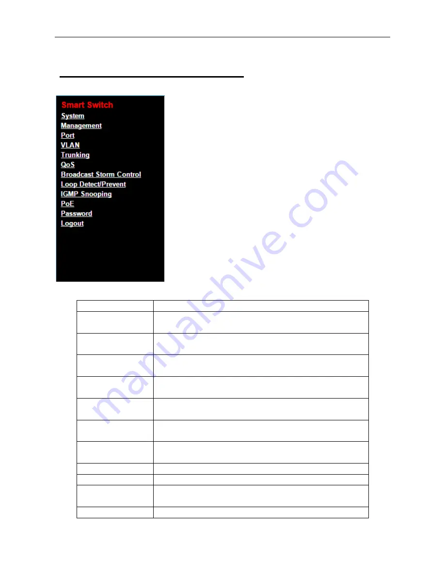
The left column shows the configuration menu. The top row shows
the switch’s current link status. Green squares indicate the port link is
up, while black squares indicate the port link is down. Below the
switch panel, you can find a common toolbar to provide useful
functions. The rest of the screen area displays the configuration
settings.
System
This link takes you to a screen where you can configure device name and ip.
Management
This link takes you to screens where you can perform firmware and
configuration file maintenance as well as reset and reboot the system.
Port
This link takes you to a screen where you can check Link Status, TX/RX
counter, Loop Status and Loop Reset.
VLAN
This link takes you to screens where you can configure port-based or
802.1Q VLAN.
Trunking
This link takes you to screen where you can logically aggregate physical
links to form one logical, higher-bandwidth link.
QoS
This link takes you to screen where you can enable Port-Based QoS or
IEEE 802.1p QoS
Broadcast Storm Control
This link takes you to screen where you can set up broadcast rate limit on
every port.
Loop Detect/Prevent
This link takes you to a screen where you can check Loop Detection and
Loop Prevention
IGMP Snooping
This link takes you to screens where you can configure IGMP Snooping.
PoE
This link takes you to screens where you can configure PoE.
Password
This link takes you to screens where you can change the system login
password.
Logout
Logout system.


