background image

5

5

Installation

1. Operating Environment

ER-5390S must be installed and operated within the limits of specified operating
temperature and humidity (see previous section under Specifications). Do not place
objects on top of the unit. Do not obstruct any vents at the sides of the unit. Do not
position the hub near any heating source such as heater, radiator, or direct exposure
to sun. Prevent entering of water and moisture into the unit. If necessary, use
dehumidifier to reduce humidity.

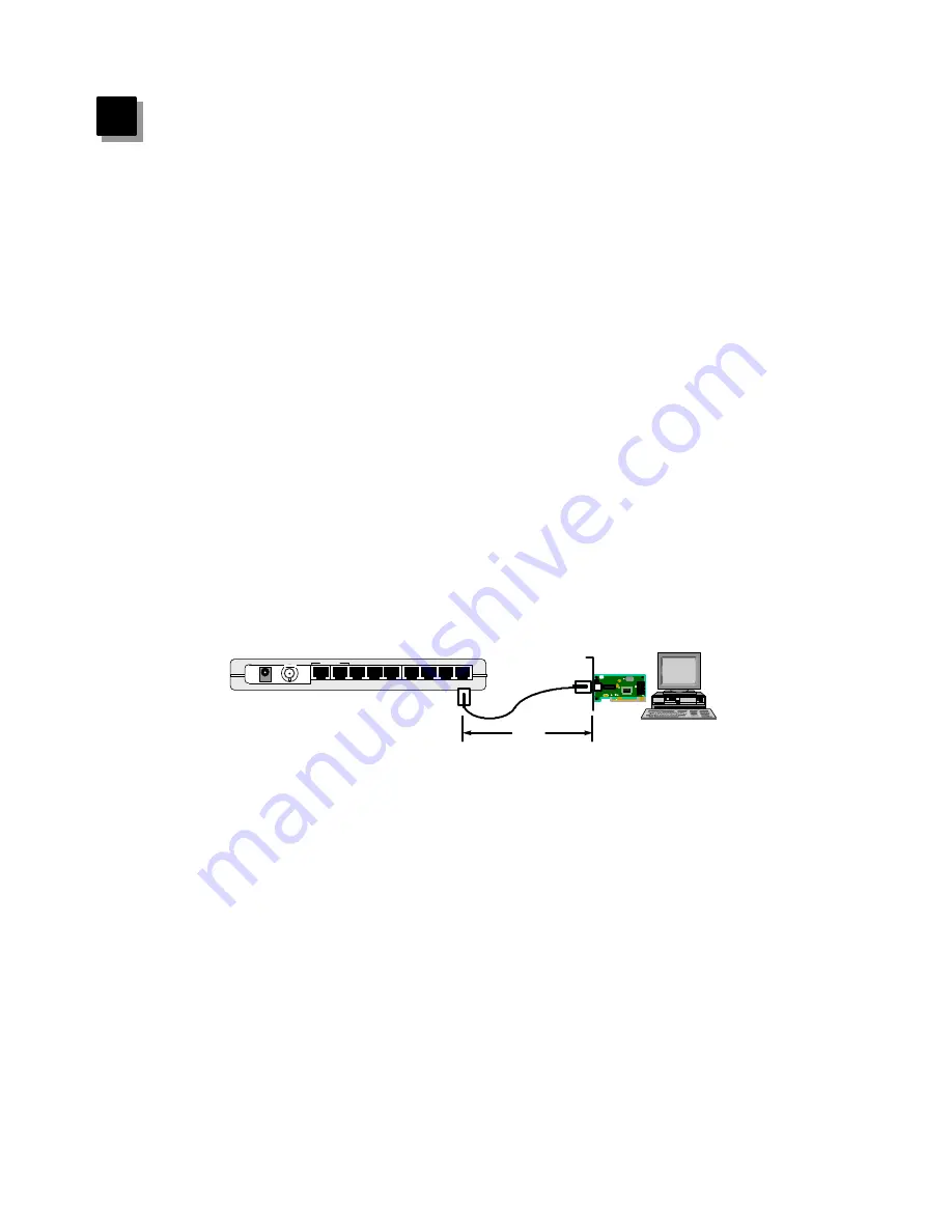
2. Connecting to network devices with UTP cable

Connect one end of the network cable to any of the RJ-45 ports on the rear panel,
and connect the other end of the network cable to the RJ-45 port of the network
device. The network cables must comply with EIA/TIA 568 specifications and
minimum Category 3 standard for 10Mbps data transmission.   Maximum length
between the hub and workstation is 100 meters (300ft).  Once the network cable is
connected on both ends and the attached network devices are powered on, the green
LNK/Rx (Link Status) LED should be lit.

3.  Uplink to Another Hub with UTP cable

Use uplink port to connect to another hub as illustrated in Figure 1-2. Connect one
end of the network cable to the uplink port and connect the other end to any of the
regular port in the other hub (except the uplink port).  Connecting cable must comply
with EIA/TIA 568 specifications and Category 3 standards to connect the hubs.
Once the network cable is connected and both hubs are powered on, the green
LNK/Rx (Link Status) LED should be lit.   Do not use the uplink port and 8th port at
the same time.

NOTE : The maximum length of the uplink cable shall not exceed 100 meters (300
              feet).

6

Figure 5-1  Connect the hub and network device

8

7

6

5

4

3

2

1

Uplink

OUT

IN

10/100 FAST ETHERNET CARD

FCC ID :

RTL8139

100m

Category 3

EIA/TIA 568

UTP Cable

Network
Adapter

Summary of Contents for 9-Port Desktop Ethernet Hub ER-5390S

Page 1: ...DIMAX Ethernet Hub ER 5390S 9 Port Desktop Ethernet Hub User s Manual S S L A N P R O F E I O N A L...

Page 2: ...tion If you suspect this equipment is causing interference turn your hub on and off while your radio or TV is showing interference to determine the source of the interference You can try to correct th...

Page 3: ...Chapter 1 Introduction 1 Chapter 2 Features Specifications 2 Chapter 3 Package Contents 3 Chapter 4 Physical Description 4 Chapter 5 Installation 6 Chapter 6 Trouble shooting 8 Contents...

Page 4: ...ed in Figure 1 1 Several ER 5390S can be connected together using the BNC ports to support a larger network An uplink port located right next to the 8th RJ 45 port allows easy connection to other hubs...

Page 5: ...of LEDs provide an easy diagnostic on the hub s and individual port s status n Slim and Compact design n Wall mountable n Two year warranty 2 Specification n Standards IEEE 802 3 n 10Mbps Ports RJ 45...

Page 6: ...op Ethernet Hub n One external power adapter n One T Connector n User s manual 3 Figure 3 1 Package contents Power Collision LNK Rx Partition Rx 9 Port 10Mbps Ethernet Hub 1 BNC DIMAX 2 3 4 5 6 7 8 L...

Page 7: ...rnet Hub 1 BNC DIMAX 2 3 4 5 6 7 8 L A N P R O F E S S I O N L Partition 4 4 Physical Description 1 Panel 4 Figure 4 1 Panel description 8 7 6 5 4 3 2 1 Uplink OUT IN Power LED Collision LED Link Rece...

Page 8: ...s Description Power Partition RJ45 Port Link Act RJ45 Port Collision Green Green Red Yellow Lit Off Lit Off Lit Off Flash Lit Off Power is supplied No power A valid link is established Data packets re...

Page 9: ...ransmission Maximum length between the hub and workstation is 100 meters 300ft Once the network cable is connected on both ends and the attached network devices are powered on the green LNK Rx Link St...

Page 10: ...the open end of T connector with a 50 ohm terminator Note Do not connect coaxial cable directly to the BNC port without using T connector 5 Connecting the power Connect the DC power jack to the DC po...

Page 11: ...ss there s data transmission on the coaxial cable 3 Uplink 8th port s LNK Rx LED is not lit after uplink to another hub l Check the network cable make sure it is properly connected to both hubs One en...

Page 12: ...ove all the network cables connect the cables back one by one to isolate the source of the collision l Check the network cable inferior cable quality will result in excessive collision and error packe...

Reviews: