background image

- 52 

-

ENGLISH

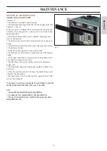
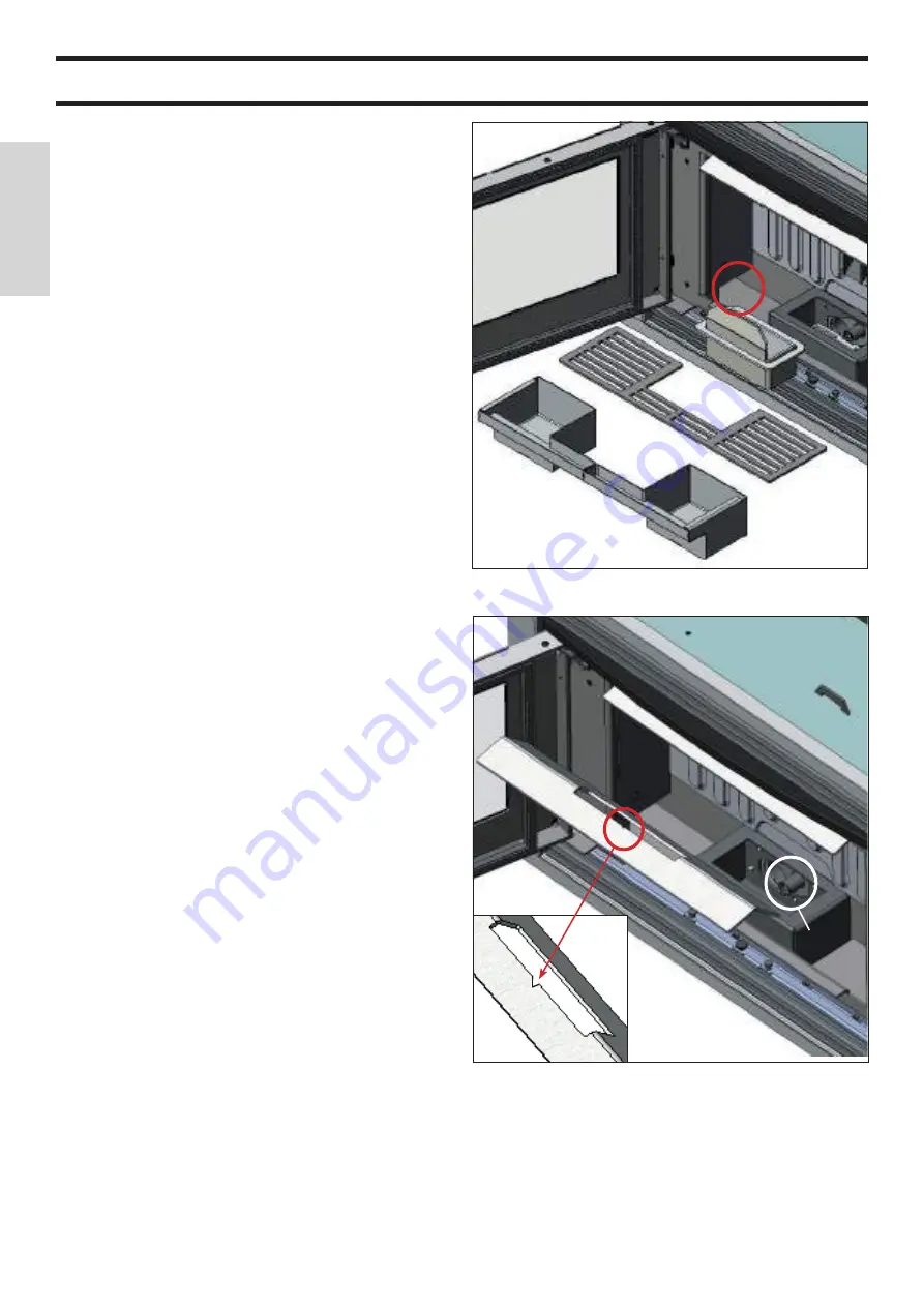
fig. A

MAINTENANCE

Before performing any maintenance, disconnect the ap-
pliance from the mains.

Regular maintenance is required for the insert to function 
correctly.

Any problems resulting from lack of maintenance will im-
mediately void the warranty.

DAILY MAINTENANCE

Operations must be performed when the stove is off, cold
and unplugged from the power supply
• Cleaning must be carried out with a vacuum cleaner (see
optional extras page 58).

• Open the door, extract the firebox (1 - fig. A) and tip the

residue into the ash drawer (2 - fig. A).

• DO NOT EMPTY THE RESIDUE OUT INTO THE PEL-
LET HOPPER.
• Remove the ash grill (3 – Fig. A), clean any debris clogging 
the holes. 

• Pull the ash drawer (2 - fig. A) out and empty it into a nonfl

ammable container (the ash may still have some parts that are
hot and/or embers).
• 

Vacuum the inside of the fireplace, the hearth, the space 

around the crucible and in the side inspections (4 - fig. A) whe

-

re the ash falls.
NB: the two ash drawers must be repositioned so as to 
approach them as much as possible to the side walls where 
there occur the inspections. 

• Remove the firebox (1 - fig. A) and remove any encrustation

using the brush provided, clearing any clogging in the holes.

• Vacuum the firebox, clean the contact edges between the fire 

box and its seating.
• Clean the glass, if necessary (when cold).

We remind you that using without cleaning the melting pot, 
may cause a sudden ignition gas inside the combustion cham-
ber with the consequent breaking of the glass.

Never vacuum hot ash, it can make the vacuum cleaner

breakdown and represents a fire risk.

ATTENTION:
MAKE SURE THE ASH TRAY IS CORRECTLY POSI-
TIONED IN ITS HOUSING

WEEKLY MAINTENANCE

• Clean the combustion chamber (with brush).
• Vacuum the hose located near the electrical resistance (5 -

fig. B).

• Remove the ceiling (6 - fig. B) and tip the residue into the ash

drawer.
N:B: reposition the ceiling with the arrow pointing out-
wards
• Clean the combustion chamber

fig. B

1

2

2

3

5

6

4

Summary of Contents for PELLKAMIN 10

Page 1: ...nstallazione uso e manutenzione pag 2 UK Installation use and maintenance pag 31 F Installation usage et maintenance pag 60 E Instalación uso y mantenimiento pag 89 D Installations Betriebs und Wartungsanleitung pag 118 NL Installatie gebruik en onderhoud pag 147 DK Installation brug og vedligeholdelse pag 176 P Instalação uso e manutenção pag 205 GR Εγκατάσταση χρήση και συντήρηση σελ 234 ...

Page 2: ...EK 124 Ref data tag plate In addition it is hereby declared that the wood pellet fireplace PELLKAMIN is in compliance with the requirements of the European directives 2014 35 UE Direttiva Bassa Tensione 2014 30 UE Direttiva Compatibilità Elettromagnetica EDILKAMIN S p a will decline all responsability of malfunctio ning or damage to the equipment in case of unauthorized substitution assembly or mo...

Page 3: ...st be performed by an authorized Edilkamin Technical Assistance Centre Failure to do so will void the warranty Commissioning as specified in standard UNI 10683 consists in a series inspections to be performed with the insert installed in order to ascertain the correct operation of the system and its compliance to applicable regulations Incorrect installation incorrect maintenance or improper use o...

Page 4: ...down naturally Each time the insert is removed a security system cuts off the power supply Should the insert be removed involuntarily du ring ignition operation or while switching off including while blocked the Power failure block phase will be launched when the insert is reinserted Wait for the block phase to end before reactivating the insert SAFETY INFORMATION The insert must not function if t...

Page 5: ... tank A is situated to the rear of the insert The hopper can be filled in the following ways through extraction of the insert see page 42 TO BE CARRIED OUT ONLY WITH THE INSERT TURNED OFF using the pellet loading kit optional complete with loading mouth to apply to the mantel see page 43 THE INSTALLATION OF THE KIT ALLOWS PEL LETS TO BE LOADED IN THE HOPPER FROM THE FRONT WITHOUT HAVING TO TURN OF...

Page 6: ...ric pressure installations at high altitude etc The standards for installation must be respected The LEONARDO system is also able to recognise the type of pellets and automatically adjust the fl ow moment by moment to ensure the required level of combustion ELECTRONIC EQUIPMENT patented AUX PORT connected via optional serial port cable code 640560 This is a clean potential free contact useful for ...

Page 7: ...mi Ø 80 mm 8 3 presa aria esterna Ø 40 mm 52 46 49 3 4 7 9 29 presa aria esterna Ø 40 mm 3 52 presa aria esterna Ø 40 mm 74 52 46 49 3 4 7 74 3 uscita fumi Ø 80 mm 8 6 9 29 presa aria esterna Ø 40 mm 3 46 3 FRONT PELLKAMIN 10 52 74 74 3 uscita fumi Ø 80 mm 8 6 46 3 Combustion air Ø 40 mm Smoke outlet Ø 80 mm Combustion air Ø 40 mm ...

Page 8: ...in the combustion chamber SAFETY THERMOSTAT Intervenes when the temperature within the insert is too high Blocks pellet loading causing the insert to turn off ROOM TEMP DETECTION PROBE located on the remote control Alternatively it can be connected up to the electronic board inside the insert GENERAL INFORMATION The heatable room dimensions are calculated on the basis of home insulation in complia...

Page 9: ...inadequate earthing system can cause anomalies for which Edilkamin cannot be held liable Power variations greater than 10 can cause problems for the product AIR INTAKE NON AIRTIGHT INSTALLATION An air intake must be prepared behind the insert and connected with the outside It must have a useful minimum section of 80 cm to guarantee sufficient air to the insert for combustion without creating depre...

Page 10: ...stic The only horizontal section allowed may be up to 2 m long up to three 90 bends in relation to the vertical A vertical section of at least 1 5 m and an anti wind terminal is necessary if the discharge outlet is not in a chimney flue reference UNI 10683 The vertical duct can be internal or external If the smoke channel is outside it must be appropriately insu lated If the smoke channel is fitte...

Page 11: ...A Fig 1 Secure the base plate A Fig 2 on the base using bolts through the holes positioned on the perimeter of the plate X Fig 5 Alternatively to secure the above plate you can use the exist ing holes in the same base plate Y Fig 5 and countersunk screws the screw head must not protrude more than 2 mm from the base plate The customer can make other holes being careful not to do so in line with the...

Page 12: ...e lower grille G fig 6 and pull the insert towards you as far as it will go fig 7 Using the handle G Fig 6 pull the insert towards you until it stops Fig 7 Each time the insert is removed a security system cuts off the power supply Should the insert be removed invo luntarily during ignition operation or while switching off including while blocked the Power failure block phase will be launched when...

Page 13: ...let loader on the mantel ATTENTION THE OPERATION MUST BE PERFORMED BEFORE INSTALLING THE INSERT To fit proceed as follows Install the bracket for centring the pellet loading tube I Fig 8 on the base plate A Fit the pellet loading tube L fig 9 on the collar of the bracket collar H fig 8 securing it with the clamp supplied M fig 8 Proceed with the installation of the insert Fig 10 11 as described in...

Page 14: ... inlet will be attached complete the mantel only after verifying the correct opera tion of the entire loading system Make a 18 5 x 18 5 cm hole Secure the loading inlet to the mantel using the self tapping screws supplied using the holes on the mantel frame reinforce the plasterboard attaching metal profiles on the rear fig 13 2nd phase INSTALLING THE LOADING TUBE fig 13 and 14 Secure the flexible...

Page 15: ... 43 ENGLISH INSTALLATION DIAGRAM FOR MAKING THE FIXING SLOT OF THE INLET WITH PELLET LOADING DOOR approximate measurements FRONT RIGHT SIDE ...

Page 16: ...vent surround frame ATTENTION THE OPERATION MUST BE PERFORMED BEFORE INSTALLING THE INSERT To fit proceed as follows Remove the slotted in upper grille N Fig 15 the lower grille O Fig 15 and the metal profile plate Y Fig 15 using the screws Take care not to overtighten the bolt securing the top grille and deform it it must be possible to unscrew it screw it back in during maintenance Remove the ve...

Page 17: ... pellet loading drawer in place of the one previously removed Refit the slotted in upper grille N Fig 21 the lower grille O Fig 21 and the metal profile plate Y Fig 21 using the screws previously removed Open the pellet front loading drawer S Fig 22 load the pellets by pushing them inside the drawer using the scoop provided T Fig 22 ...

Page 18: ...this the air circulation grill must be included as previously specified THE MANTEL CAN BE CONSTRUCTED WITH FIRE RESISTANT PANELS IN PLASTERBOARD OR GYPSUM BOARD AERATION GRILLES FOR PREVENTING ANY EXCESS TEMPERATURE INSIDE MUST BE PROVI DED FOR DURING CONSTRUCTION fig 23 During the construction phase of the covering it is funda mental to ensure that the combustion air is restored to prevent pressu...

Page 19: ...anchors in order to prevent it from tipping over Place the top of the base 2 Fig 25 adjusting it to the desired height using the bolts provided 3 Fig 25 At this point proceed with the installation on the base using the bolts supplied of the base plate A Fig 26 supplied with the insert Continue with the installation of the insert as shown on page 41 Failure to follow the above instructions can caus...

Page 20: ...ves must be recalibrated using a similar procedure to that carried out by the DEALER when the insert is ignited the first time Using unsuitable pellets may decrease efficiency cause malfunctions stop the stove from functioning due to clogging dirt on the glass unburnt fuel etc A simple visual analysis of the pellets may be carried out Good quality smooth uniform length not very dusty Poor quality ...

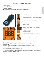
Page 21: ...ntrol on stand by to remote control on to increase decrease the various regulations A to select Automatic function M to select Manual function and access the control and programming menus The display also shows other useful information in addition to the icons described above Stand by position shows room temperature 20 C kg of pellets 15 kg remaining in tank and current time 15 33 Manual work phas...

Page 22: ... process of turning off OPERATIONS THAT CAN ONLY BE CARRIED OUT BY REMOTE CONTROL Clock regulation Press and hold the key M for 2 seconds to access the Clock menu This allows you to set the internal electronic board clock By then pressing the key M the following data appe ars in sequence and can be regulated day month year hour minutes day of the week The wording SAVE will appear for confirmation ...

Page 23: ... road test After this the tank can be filled completely and the PELLKA MIN started up When running at the time at which a whole 15 kg sack of pel lets can be loaded the display will show the word Reserve flashing At this point after having poured in a sack of pellets you need to inform the memory that you have loaded 15 kg To do so proceed as follows 1 press the M key for approximately 3 4 seconds...

Page 24: ...rucible and in the side inspections 4 fig A whe re the ash falls NB the two ash drawers must be repositioned so as to approach them as much as possible to the side walls where there occur the inspections Remove the firebox 1 fig A and remove any encrustation using the brush provided clearing any clogging in the holes Vacuum the firebox clean the contact edges between the fire box and its seating C...

Page 25: ...hopper and vacuum the bottom Clean the smoke extractor fan compartment check the thermo couple Clean inspect and remove encrustations on the ignition resist ance chamber replace if necessary Visually inspect the electric wiring connections and power supply cord Clean the pellet hopper and check play together with the screw gear motor Check the small pressure switch pipe and replace if necessary Re...

Page 26: ...ails to appear within a maximum of 15 minutes or if ignition temperature is not reached Problem Turns off due to incorrect smoke temperature during ignition Distinguish either of the following cases Flame does NOT appear Actions Check combustion chamber position and cleanliness arrival of combustion air in the combustion chamber if the heating element is working DEALER room temperature if lower th...

Page 27: ...s If the signal appears at every start up contact the TAC for having the combustion air intake circuit checked it may be obstructed by dust or other foreign bodies 13 Problem NO DRAUGHT This signal appears when during self diagnosis performed each time the product starts up the depressurisation value measured inside the combustion chamber is below the expected value If this signal appears when str...

Page 28: ...or is closed properly The combustion chamber is inserted properly into the relevant compartment REMEMBER TO VACUUM THE COMBUSTION CHAMBER BEFORE EACH IGNITION Should ignition fail DO NOT re ignite until you have emptied the combustion chamber In accordance with art 26 of Legislative Decree no 49 of 14th March 2014 Implementation of Directive 2012 19 UE on the disposal of electrical and electronic ...

Page 29: ... INSTALLER DATE AND STAMP CAT FIRST IGNITION DATE AND STAMP ANY SERVICING DATE AND STAMP SEASONAL MAINTENANCE DATE AND STAMP DEALER DATE AND STAMP CAT For further clarification or requirements visit our website www edilkamin com NOTES ...

Page 30: ......

Page 31: ......

Page 32: ... 254 cod 941198 GB 12 17 H w w w e d i l k a m i n c o m ...

Reviews: