3. Based on the number of functional ports, connect on end of the T1 cable(s) to the T1
port(s) and the other end of the cable(s) to the T1 demarcation unit provided by the
Service Provider.
To reduce the risk of fire, connect the T1 port to the T1 network using only 26
AWG or larger wire such as 24, 22, 20, etc.
4. Skip to step 8.
5. Connect an Ethernet cable between the Ethernet WAN port of 4562, shown in the above
diagram as “D,” and the Ethernet port on a router or a modem.
6. Connect the PSTN lines to ports denoted by “H” in the above diagram.
7. Connect the regular phones or key system to ports denoted by “I” in the above diagram.
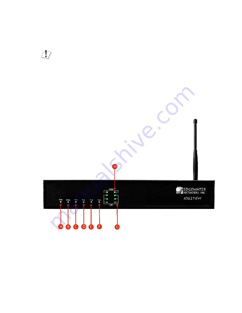
8. Plug one end of the power adapter into an AC outlet and the other end into the power
receptacle on 4562. Make sure that the power and status LEDs, shown in the diagram
below as “A” and “B”, are solid green after a short while.
Page 4 of 7


