4-29
Utilizing the Applanix POSVIEW software set the ethernet real-time broadcast to groups 3,7,10, and 102.
The output rate of the POS-MV should be set to 50Hz. The POS-MV must also be set to Falling (Negative)
Edge or
Active Low
for the 1PPS as the 6205s defaults to sync on the falling edge. The POS-MV must also
be set to UTC (default), not GPS, for the main time frame.
See POS MV V5 User Interface Control Document (PUBS-ICD-004089) latest revision for full details of data
telegrams. In summary, the POS-MV groups are:
•
Group 3 = Primary GNSS status, used for time field for time sync
•
Group 7 = PPS time recovery and status. Not used by EdgeTech
•
Group 10 = General Status and FDIR
•
Group 102 = Sensor 1 time, position, velocity, attitude, heave & dynamics, used for position and
attitude.
For more information, refer to the
4.2.3.3
PPS Port Configuration
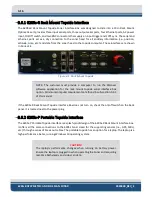
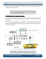
Pulse per second (PPS) is a feature in many GPS units to provide an accurate timing signal to synchronize
various devices to a precise, common clock. The Edgetech 6205s-R rack-mounted and 6205s-P portable
topsides provide a rear panel 1PPS port to physically connect to a PPS capable unit. The 6205s-R is
depicted in
. The logical configuration is done in the attached GPS’s configuration and activating
the 1PPS option in
CAUTION!
The 6205S system is optimized to work with a falling edge
1PPS signal.
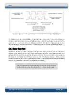
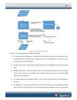
The EdgeTech Isolator Board is designed to identify the input signal's falling edge and reconstitute it as a
rising edge 2.27ms pulse. This signal is passed down the deck cable to the subsea electronics, where the
rising edge is utilized as the 1PPS time sync reference. Refer to
. This configuration produces
little to no latency when a falling edge 1PPS signal is injected at the topside.
NOTE:
To learn more about the EdgeTech Isolator Board, refer to the
Summary of Contents for 6205S
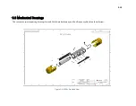
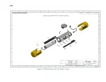
Page 37: ...3 20 Figure 3 5 6205s Exploded View with Adaptor Flange...
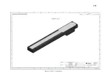
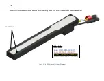
Page 38: ...3 21 Figure 3 6 6205s Transducer...
Page 40: ...3 23 Figure 3 8 6205s Wiring Diagram 0019627...
Page 86: ...8 69 Figure 8 22 Checking all COM Ports...
Page 92: ...8 75 Figure 8 28 UDP broadcast settings example Figure 8 29 Eth1 data output...
Page 94: ...8 77 Figure 8 31 1PPS settings example Falling Edge and 1msec duration...

