3-10
2000-DSS Combined Sonar
0009335_REV_D
6.
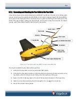
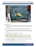
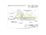
Attach the eyelet of the tow rope and the loop of the safety grip to the shackle on the towing arm
and secure the shackle bolt with seizing wire or a tie wrap.
7.
Lay the tow cable over the tow bridle and secure it in three or more places with tie wraps.
3.7.2
Connecting the 2000 Topside Processor
To connect the 2000 Topside Processor:
1.
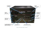
Verify that the Topside Processor and the 2000 Digital Telemetry Link are not connected to AC
power.
2.
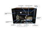
Verify that the tow cable is properly connected and attached to the tow vehicle, and then connect
the tow cable adapter to the tow cable and to the SEA CABLE connector of the 2000 Digital
Telemetry Link.
3.
If an external source will be used to trigger an external device attached to 2000 DSS Tow Fish,
connect the trigger output of this source to the SYNC connector.
4.
Connect one LCD monitor to the MONITOR 1 connector of the Topside Processor and the second
LCD monitor to the MONITOR 2 connector.
5.
Connect the trackball to the USB connector.
6.
Connect the keyboard to the USB connector.
7.
If a printer will be used, connect it to a free USB port. For information on the printers that can be
connected to the Topside Computer, refer to appendix
8.
If a navigation system will be used, connect the navigation system output to the COM 1-NAV
connector.
9.
Connect the Ethernet patch cable to the DATA connector of the 2000 Digital Telemetry Link and
to the ETHERNET 1 connector of the Topside Processor. This cable may be extended up to 100
feet using a Category 5 Ethernet crossover or straight patch cable.
10.
Connect an AC power cord to the VAC INPUT connector of the Topside Processor and to the AC
power source.
11.
Connect an AC power cord to the LINE VAC connector of the 2000 Digital Telemetry Link and to
the AC power source.
12.
Connect an AC power cord to each of the LCD monitors and to the AC power source.
Summary of Contents for 2000-DSS
Page 20: ......
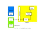
Page 56: ...Figure 4 2 2000 Digital Telemetry Link Electronics Block Diagram...
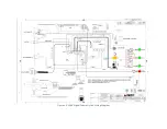
Page 57: ...Figure 4 3 2000 Digital Telemetry Link Wiring Diagram...
Page 59: ...Figure 4 4 Tow Vehicle Electronic Block Diagram...
Page 60: ...Figure 4 5 Tow Vehicle Interconnect Drawing...
Page 63: ...Figure 4 6 Armored Cable PMI Grip Unterminated Topside...
Page 64: ...Figure 4 7 Test Cable...
Page 77: ...5 13 Figure 5 16 Magnetic Declination Estimated Value Screen...
Page 79: ...5 15 getDeclination CR Figure 5 18...
Page 80: ......
Page 94: ......
Page 96: ......
Page 98: ......

