3-6
2000-DSS Combined Sonar
0009335_REV_D
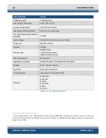
3.5.2
Topside Computer Controls and Indicators
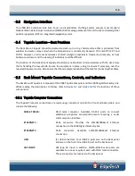
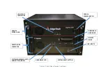
The Topside Computer controls and indicators are the following:
POWER:
Rocker switch. Switches AC power to the Topside Processor. This
switch can be left in the on position at all times.
SYSTEM POWER
(
switch
)
:
Push button toggle switch. Turns the Topside Processor on or off.
SYSTEM POWER
(
indicator
)
:
Green indicator. Illuminated when the Topside Processor is on.
RESET:
Momentary push button switch. Resets the Topside Processor.
HDD:
Yellow indicator. Flashes when a hard drive on the Topside
Processor is being accessed.
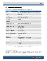
3.5.3
2000 Digital Telemetry Link Connections
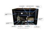
The 2000-DL connections are as follows:
SEA CABLE:
SubConn MCBH4F female connector to the sea cable that goes
down to the towfish.
SYNC:
Provides an input connection for a TTL external trigger that is
sent to the towfish (used to trigger external device attached to
2000 DSS Tow Fish).
DATA:
RJ-45 Standard ETHERNET connection used for connecting to the
topside computer below it.
LINE VAC:
CEE-type AC input connector. Connects to 90–260 VAC, 50/60 Hz
power.
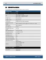
3.5.4
2000 Digital Telemetry Link Controls and Indicators
The 2000 Digital Telemetry Link includes controls and indicators include the following:
LINE:
Rocker switch. Switches AC power to the POWER switch on the
front panel of the 2000-DL. This switch can be left in the on
position at all times.
POWER:
Rocker switch. Turns the 2000-DL on or off.
PWR:
Green indicator. Illuminated when the 2000-DL is on.
Summary of Contents for 2000-DSS
Page 20: ......
Page 56: ...Figure 4 2 2000 Digital Telemetry Link Electronics Block Diagram...
Page 57: ...Figure 4 3 2000 Digital Telemetry Link Wiring Diagram...
Page 59: ...Figure 4 4 Tow Vehicle Electronic Block Diagram...
Page 60: ...Figure 4 5 Tow Vehicle Interconnect Drawing...
Page 63: ...Figure 4 6 Armored Cable PMI Grip Unterminated Topside...
Page 64: ...Figure 4 7 Test Cable...
Page 77: ...5 13 Figure 5 16 Magnetic Declination Estimated Value Screen...
Page 79: ...5 15 getDeclination CR Figure 5 18...
Page 80: ......
Page 94: ......
Page 96: ......
Page 98: ......

