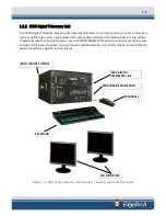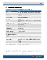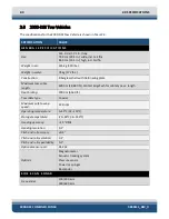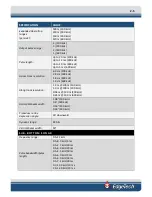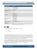
1-5
1.2.4
Tow Cables
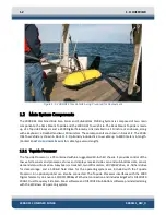
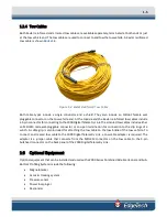
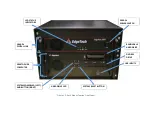
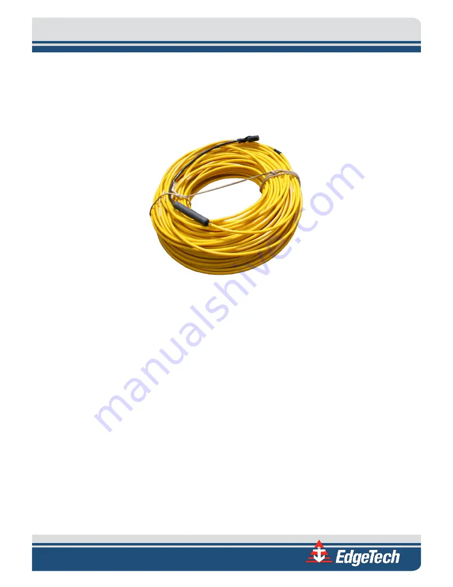
Both Kevlar reinforced and armored tow cables are available separately, terminated at both ends or just
at the tow vehicle end. The tow cables are used to connect to and tow the tow vehicle. A Kevlar reinforced
tow cable is shown
Figure 1-4: Kevlar Reinforced Tow Cable
Both cable types include a single conductor and a shield. They also include an MCIL6F female wet
pluggable connector on the tow vehicle end. At the topside end the Kevlar reinforced tow cables include
a 5-pin connector for connecting to the 2000 Digital Telemetry Link. The armored tow cables include either
an MCIL4M male wet-pluggable connector or an open termination for connection to the slip rings of a
winch. A cable grip is also included for attaching the tow cable to the tow bridle of the tow vehicle. To
connect an armored tow cable to the 2000 Digital Telemetry Link, a tow cable adapter is required. The
adapter is a jumper cable that connects from the MCIL4M connector on the tow cable to the 5-pin
bulkhead connector on the back panel of the 2000 Digital Telemetry Link.
1.3
Optional Equipment
Optional equipment that can be installed and used with a 2000 Series Combined Side Scan Sonar and Sub-
Bottom Profiling System include the following:
•
Magnetometer
•
Acoustic tracking system
•
Pressure sensor
•
Power loss pinger
•
Responder
Summary of Contents for 2000-DSS
Page 20: ......
Page 56: ...Figure 4 2 2000 Digital Telemetry Link Electronics Block Diagram...
Page 57: ...Figure 4 3 2000 Digital Telemetry Link Wiring Diagram...
Page 59: ...Figure 4 4 Tow Vehicle Electronic Block Diagram...
Page 60: ...Figure 4 5 Tow Vehicle Interconnect Drawing...
Page 63: ...Figure 4 6 Armored Cable PMI Grip Unterminated Topside...
Page 64: ...Figure 4 7 Test Cable...
Page 77: ...5 13 Figure 5 16 Magnetic Declination Estimated Value Screen...
Page 79: ...5 15 getDeclination CR Figure 5 18...
Page 80: ......
Page 94: ......
Page 96: ......
Page 98: ......

